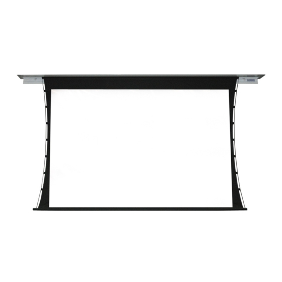
Draper Ultimate Access XL V Talimatlar Kılavuzu - Sayfa 5
Projeksiyon Perdesi Draper Ultimate Access XL V için çevrimiçi göz atın veya pdf Talimatlar Kılavuzu indirin. Draper Ultimate Access XL V 7 sayfaları. 220v electric projection screen
Ayrıca Draper Ultimate Access XL V için: Talimatlar Kurulum ve Çalıştırma (7 sayfalar)

Ultimate Access XL E & V
Electric Projection Screen
Section 8 - Limit Adjustments
Please Note: Screen limits are factory set. Instructions below for
minor adjustments only. Please check with Draper prior to resetting
screen limits.
Please Note: If Access XL E/V is "Right Hand Motor," the WHITE/DOWN
and YELLOW/UP
(II)
limit screws are reversed
Section 8.1 - Limit Adjustments
Section 8.1.1 - "Down" Limit Adjustment
To Reduce Screen Drop:
1. Raise screen surface approximately
1'
(30 cm)
above desired setting and
turn off.
2. Turn DOWN
(I)
limit screw clockwise
(3 screw turns =
/
roller
revolution).
1
2
3. Test by lowering screen. Repeat
steps 1 & 2 until desired position is
reached.
Section 8.1.2 - "Up" Limit Adjustment
If Screen Raises Too High:
1. Lower screen surface approx.
1'
(30 cm)
below desired setting
and turn off.
2. Turn UP
(II)
limit screw clockwise
(3 screw turns =
1
/
roller
2
revolution).
Caution: DO NOT allow dowel to wrap over roller when operating screen! This could damage screen.
(I)
(Fig.
9).
(requires a
5
/
" (4 mm) Allen wrench)
32
To Increase Screen Drop:
1. Lower screen to down limit.
2. With down switch on, turn DOWN
screw counterclockwise
(3 screw turns =
/
roller revolution)
to increase drop.
1
2
3. Test by raising screen approximately
1'
(30 cm)
then down to new down limit.
4. Repeat steps 2 and 3 until desired
position reached.
3. Test by advancing screen up.
4. Repeat steps 1 through 3 until
desired position is reached.
Caution:
- Be sure all switches are in "off" position before adjusting limit switches.
- Be prepared to shut off manually while testing.
- Screen may be damaged by lowering it too far and exposing roller.
- Motor must be installed so limit switches are pointed down.
Figure 9
Motor
End
n c
d i e
(I)
limit
A u
e
S i d
Standard Roll
Left hand motor:
White Socket—Down
Yellow Socket—Up
Right hand motor:
White Socket—Up
Yellow Socket—Down
If Screen Needs to Raise Higher:
1. Lower screen surface
2. With Up switch on,
approx. 1'
(30 cm)
turn UP
below desired setting
counterclockwise
and turn off.
(3 screw turns =
roller
page 5 of 7
Motor
End
e
c k
B a
d e
S i
Reverse Roll
Left hand motor:
White Socket—Down
Yellow Socket—Up
Right hand motor:
White Socket—Up
Yellow Socket—Down
3. Repeat steps 1 and 2
(II)
limit screw
until desired position
is reached.
1
/
2
revolution).
Motor
End
A
Waterf
Left hand m
White Soc
Yellow So
Right hand
White Soc
Yellow So
