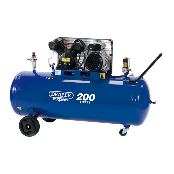
Draper 77711 Talimatlar Kılavuzu - Sayfa 7
Hava Kompresörü Draper 77711 için çevrimiçi göz atın veya pdf Talimatlar Kılavuzu indirin. Draper 77711 16 sayfaları. 100, 150 & 200 litre compressors

POSITIONING:
Do not stand the compressor on any surface
with a 15° or greater tilt as this will lead to
possible running problems.
Allow a minimum gap of 50cm around the
compressor to aid connection and airflow.
In addition to pneumatic air tools, your
compressor may be connected to several
accessories suitable for blowing, washing
and spraying for example.
For technical specifications and detailed
instructions, please refer to the instructions
provided with the individual accessory.
After unpacking the compressor for the first
time it will be necessary to remove the plastic
transit bung and replace it with the dipstick
supplied.
NOTE: It is advisable to store this bung,
should the compressor require transporting
in the future.
Make sure that the level of oil ranges
between the max. and the min. mark (Fig.1).
After the first 50 working hours, replace the
oil with one of those listed (see page 10).
When the installation procedure is complete,
the compressor is ready for use. Make sure
the pressure switch is positioned 'OFF'. Switch
on the power then position the pressure
switch to the 'ON' position to start the
compressor (Fig.2).
When starting the compressor for the first
time, leave it running for about 10 minutes
with the air tap (A) or the bung on the
underside of the tank completely open
(Fig.3). After this time, close air tap (A) and
make sure that pressure in the tank is correct
and that the compressor stops automatically
when the max. pressure is reached. The
pressure is monitored on gauge (B) (Fig.4).
The operation is automatically controlled by
the pressure switch which stops the motor
when the max. pressure allowed is achieved,
and starts it again when the pressure goes
below the minimum threshold (about 2 bar
less than the max. pressure).
Never unplug the compressor or switch off
the main switch to stop the compressor.
Always position the pressure switch to the
off position.
OPERATION AND USE
Fig.1.
- 6 -
Fig.2.
Fig.3.
(A)
Fig.4.
(B)
