Draper 02520 Manuel - Sayfa 13
Öğütücü Draper 02520 için çevrimiçi göz atın veya pdf Manuel indirin. Draper 02520 20 sayfaları. 230v router
Ayrıca Draper 02520 için: Manuel (20 sayfalar)

8.
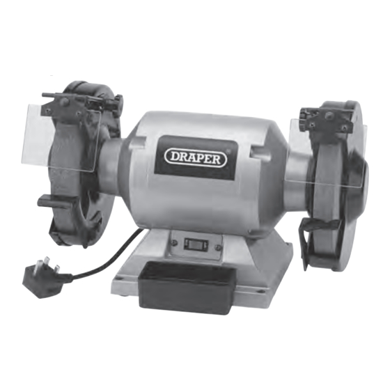
ASSEMBLING THE BENCH GRINDER
8.1
INSTALLATION
Choose a location that is level, flat and with a lot of
natural light.
The bench grinder should be operated on a work
bench that is high enough to prevent any injury
caused by working in an uncomfortable position;
but not too high that the work piece cannot be
safely viewed from above.
Warning!
Bending over or having your neck bent for too long
(from looking down) can lead to fatigue injuries.
The environment will have a negative result on its
operation if you are not careful. If the air is damp,
components will rust. If the machine is unprotected
from dust and debris; components will become
clogged: And if not cleaned and maintained
correctly or regularly the machine will not perform
at its best.
The work bench should offer enough space around
the bench grinder for all possible applications and
to house any accessories.
Although the bench grinder has been assembled in
the factory, some final assembly and adjustments
will be required before it can be used. The fine
setup will come from experimenting with your new
bench grinder and making small adjustments.
8.2
BENCH MOUNTING YOUR GRINDER – FIG. 1
Securely bolt the bench grinder to a work bench or other secure surface through the various
points in the base (fixings are not supplied).
Ensure there is enough clear space around the grinder to accommodate large items which may
be ground, i.e., garden tools, etc. To reduce any vibration, mount the grinder on a vibration
absorption mat.
8.3
FITTING THE TOOL RESTS – FIG. 2
− Attach the left and right hand tool rests using the fittings from Group (A) shown in
7.2 WHAT'S IN THE BOX section on page 12.
− Fit both tool rests (5) to the inner edge of the wheel guards using the bolts (A1) and washers
(A2) provided.
− Adjust them so there is approx. 1.5mm between the grinding wheel face and the tool rest.
Caution!
Ensure both washers are fitted between the bolt and the tool rest. Neglecting to install the
washers correctly may result in the tip of the bolt contacting the side of the abrasive wheel.
FIG.
1
(5)
(A1)
(A2)
FIG.
2
– 13 –
