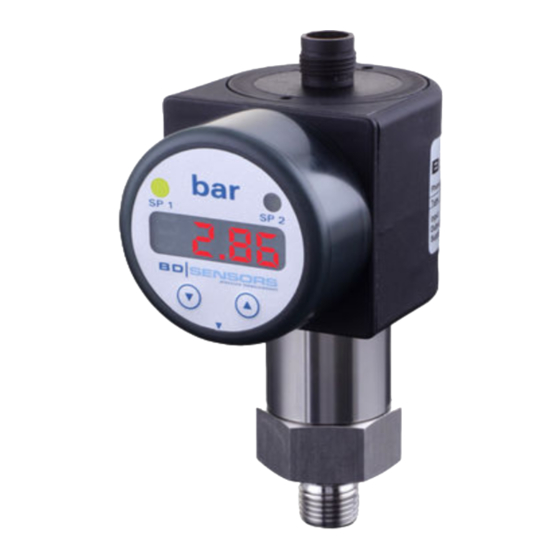
BD Sensors DS 226 Montaj Talimatları - Sayfa 2
Anahtar BD Sensors DS 226 için çevrimiçi göz atın veya pdf Montaj Talimatları indirin. BD Sensors DS 226 2 sayfaları. Electronic pressure gauge

DE EN
Návod k montáži /
Mounting instructions
Elektronické digitální manometry DM 2XX/
Electronic Pressure Gauge DM 2XX
Elektronické tlakové spínače DS 2XX a DS 4XX /
Electronic Pressure Switch DS 2XX or DS 4XX
DM 200, DM 201, DS 200, DS 200 P, DS 201, DS 201 P,
DS 202, DS 210, DS 217, DS 226, DS 400, DS 400 P,
DS 401, DS 401 P
DS 200
www.bdsensors.com
Centrála východní Evropa /
Headquarters Ostern Europe
BD SENSORS s.r.o.
Hradišťská 817
CZ - 687 08 Buchlovice
Česká republika / Czech Republic
Tel.: +420 572 / 411 011
Fax: +420 572 / 411 497
Centrála západní Evropa /
Rusko /
Headquarters Western Europe
Russia
BD SENSORS GmbH
BD SENSORS RUS
BD-Sensors-Str. 1
39a, Varshavskoe shosse
D - 95199 Thierstein
RU - Moscow 117105
Německo /
Rusko /
Germany
Russia
Tel.: +49 (0) 92 35 / 98 11-0
Tel.: +7 (0) 9 59 81 / 09 63
Fax: +49 (0) 92 35 / 98 11-11
Fax: +7 (0) 9 57 95 / 07 21
Tento návod k montáži je výtah z podrobného
návodu k obsluze. Ten si prosím stáhněte
z našich internetových stránek, pokud nejste
s výrobkem dobře seznámeni.
These mounting instructions are an excerpt from the complete
operating manual. It may be downloaded from our homepage,
if you are not familiar with the device.
www.bdsensors.cz
www.bdsensors.com
– Technické změny vyhrazeny –
– Technical modifications reserved –
English
WARNING! In order to avoid hazards to operators and
damages to the device, the following instructions have to
be performed by qualified technical personnel.
WARNING! Adhere to the safety and operating instructions
stated in the operation manual. Effective regulations on
occupational safety, accident prevention as well as national
installation standards and approved engineering tech-
niques must in addition be complied with.
Limitation of liability
If the instructions in the operating manual are not adhered
to or if the device is inappropriately used, modified or da-
maged, liability is not assumed and warranty claims will be
excluded.
Intended use
Ensure that the medium is compatible with the media-
wetted parts and that the device is suitable for the appli-
cation without restrictions. The technical data listed in the
current data sheet is binding and must definitely be obser-
ved.
Product identification
nominal
designation
ordering
pressure
code
number
range
signal
supply
connector pinout
Operating and display elements
(e.g. for DS 2XX with two contacts)
LED
unit
LED
contact 1
contact 2
4-digit seven-
segment display
▼-button
▲-button
▲-button: enter operating mode
move forward in the menu system
increase the displayed value
▼-button: enter operating mode
move backward in the menu system
decrease the displayed value
both buttons simultaneously:
confirm the menu items and set values
Mounting
WARNING! Install the device only in depressurized and currentless state!
WARNING! Use a suitable seal, corresponding to the medium and the pressure input.
Connection acc. to DIN 3852
knurled ring: tighten by hand only
wrench size of plastic: max. 3 Nm
G1/4" steel:
approx. 5 Nm
G1/2" steel:
approx. 10 Nm
G3/4" steel:
approx. 15 Nm
G1" steel:
approx. 20 Nm
Dairy pipe connection
serial
- Centre the connection
in the mounting part.
- Screw the cup nut onto the
mounting part.
- Then tighten it with a hook wrench.
Pin configuration
M12x1
Electrical
plastic
connections
(5-pin)
Supply +
1
Supply –
3
3-wire: Signal +
2
Contact 1
4
Contact 2
5
Contact 3
-
Contact 4
-
via
Shield
pressure
port
pressure port
Electrical
ISO 4400
connections
Supply +
1
Supply –
2
3-wire: Signal +
3
Contact 1
3
Contact 2
-
Contact 3
-
Contact 4
-
Shield
ground contact
Connection acc. to EN 837
G1/4": approx. 20 Nm
G1/2": approx. 50 Nm
Clamp and Varivent
connection
- Centre the connection in the
mounting part.
- Fix the device with a suitable fastening
element (e. g. semi-ring or retractable
ring clamp) according to the supplier's
instructions.
Wiring diagrams
2-wire-system (current)
M12x1
M12x1
metal
plastic
p
(5-pin)
(8-pin)
supply +
1
1
3
3
2
2
supply –
4
4
5
5
contact 1
-
6
I
-
7
contact 2
plug-
via
housing/
pressure
3-wire-system (current/voltage)
port
p
cable colours
supply+
(DIN 47100)
wh (white)
supply –
bn (brown)
signal +
gn (green)
contact 1
gr (grey)
pn (pink)
contact 2
-
contact 3
I/U
-
contact 4
gn/ye
(green/yellow)
For the electrical connection, a shielded and twisted
multicore cable is recommended.
BDS_sro_NAMO_DM2XX-DSXXX_CS-EN_290811
NPT connections
1/4" NPT: approx. 30 Nm
1/2" NPT: approx. 70 Nm
V
S
A
R
L
R
L
V
S
A/V
R
L
R
L
R
L
R
L
