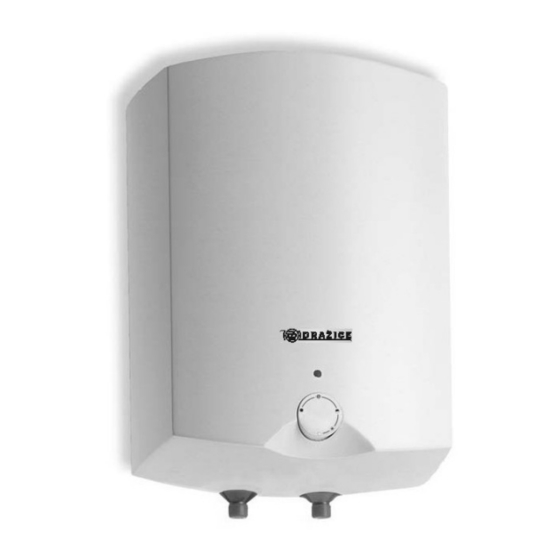
Drazice TO 10 UP Kullanım ve Kurulum Kılavuzu - Sayfa 5
Su Isıtıcı Drazice TO 10 UP için çevrimiçi göz atın veya pdf Kullanım ve Kurulum Kılavuzu indirin. Drazice TO 10 UP 8 sayfaları. Electric water heater

For proper safety valve operation, a backflow valve must be mounted on the inlet pipes, preventing spontaneous heater
draining and hot water penetrating back into the water main.
We recommend that the hot water distribution from the heater was as short as possible to minimise heat losses.
Heaters must be provided with a discharge valve mounted on the cold service water inlet to the heater for potential
disassembly or repair.
When assembling the security equipment, follow ČSN 06 0830.
8
ELECTRICAL INSTALLATION
The electric wiring scheme is attached in the manual to the water heater (Fig. 2). The heater has to be connected via
a separate supply with a front-end main switch. The heater is connected to the 230V/50Hz electric network using a
conductor with a contact plug fitted with a switch that turns off all network poles and the circuit breaker (protector).
Electric installation must comply with valid electrotechnical standards. Connection of the heater to electric network shall
be executed following the plumbing fixture. Access to the electric part of the heater is enabled only upon disconnecting
the heater from power supply and unscrewing the guard of the heater. Respect rules of protection against electrical
injuries in accordance with ČSN 33 2000-4-41.
The degree of protection of electric parts of the heater is IP 24.
9
PUTTING THE HEATER INTO OPERATION
Once connected to the water supply, the heater can be put in service.
Procedure:
a) check the power and water main installation
b) open the hot water valve on the combination faucet
c) open the cold water inlet valve to the heater.
d) As soon as the water starts running through the hot water valve, the heater is filled and the valve closes.
e) Using the front-end main switch open electricity and thus the heater activates.
10
IMPORTANT NOTICES
The hot water outlet must be equipped with a combination faucet.
It is not allowed to handle the thermostat in any manner whatsoever, aside from temperature resetting
with a control button.
All electric installation handling, adjustment and replacement of the regulation elements shall only be
performed by an authorised service company.
The thermal fuse must not be turned off. The non-reversible thermal fuse discontinues electric power input to the heating
element should the thermostat fail, if the water temperature in the heater exceeds 99°C.
Disposal of packaging material and functionless product
A service fee for providing return and recovery of packaging material has been paid for the
packaging in which the water heater was delivered.
The service fee was paid pursuant to Act No. 477/2001 Coll., as amended, at EKO-KOM a.s.
The client number of the company is F06020274. Take the product packages to a waste
disposal place designated to that purpose by the municipality. When the operation terminates,
disassemble and transport the discarded and unserviceable heater to a waste recycling centre
(collecting yard), or contact the manufacturer.
Safety valve starting
pressure (MPa)
0.6
0.7
1
5
Admissible operating
water heater pressure
(MPa)
0.6
0.7
1
Max pressure in the
cold water pipe (MPa)
up to 0.48
up to 0.56
up to 0.8
