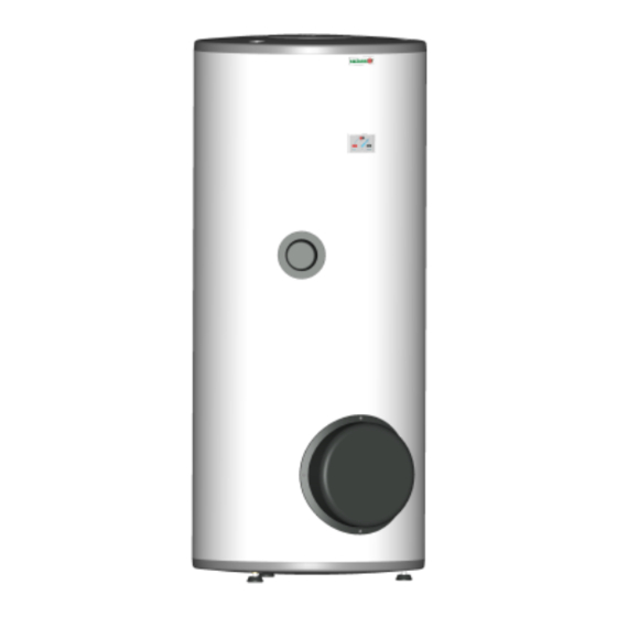
Drazice OKC 200 NTR Kullanım ve Kurulum Kılavuzu - Sayfa 9
Kazan Drazice OKC 200 NTR için çevrimiçi göz atın veya pdf Kullanım ve Kurulum Kılavuzu indirin. Drazice OKC 200 NTR 13 sayfaları. Stationary water heaters
Ayrıca Drazice OKC 200 NTR için: Kullanım ve Kurulum Kılavuzu (17 sayfalar)

8.
PRESSURE LOSSES
9.
EXAMPLES OF HEATERS CONNECTION
Connecting a heater to a heating circuit
The heater is placed on the ground, next to the heating source, or in its vicinity. The heating circuit is connected to
marked inputs and outputs of the heater exchanger; the deaerating valve is mounted in the highest place. It is
necessary to install a filter into the circuit in order to protect the pumps, the three-way valve, and backflow flaps,
and the exchanger from sedimentation. It is recommended to flush the heating circuit before the assembly. All
wiring connections must be properly insulated from heat.
If the system works with priority heating of HSW using a three-way valve, always follow the installation
instructions of the three-way valve's manufacturer.
Connecting a Heater to a Hot Water Distribution
Cold water shall be connected to an inlet marked with a blue ring and writing "HSW INLET". Hot water shall be
connected to an outlet marked with a red ring or writing "HSW OUTLET". If the hot service water (HSW)
distribution is equipped with circulation circuit, it shall be connected to the outlet marked with "CIRCULATION".
For potential drain of heater, the HSW inlet has to be provided with a "T" fixture with a drain valve. Each
individually lockable heater must be at the cold water inlet provided with a stop gate, test cock, safety valve with a
reverse flap and a pressure gauge.
An example of a group heater connection for steady hot water consumption from all tanks using
Tichelmann's method
OV – Heating water
SV - Cold water
C - circulation
TUV - Hot service water
1 - Return valve
2 - pump
9
