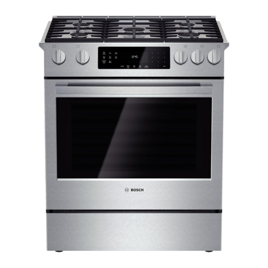
Bosch Vision 800 Series Servis Kılavuzu - Sayfa 25
Fırın Bosch Vision 800 Series için çevrimiçi göz atın veya pdf Servis Kılavuzu indirin. Bosch Vision 800 Series 36 sayfaları. Gas slide-in ranges
Ayrıca Bosch Vision 800 Series için: Kullanım Kılavuzu (40 sayfalar), Boyutlar ve Özellikler (2 sayfalar), Kurulum Kılavuzu (6 sayfalar), Servis Kılavuzu (43 sayfalar), Kurulum Talimatları Kılavuzu (28 sayfalar)

58300000194725 ARA EN B
NOTICE
The wire diagram can be found in a plastic packet taped to the
vented rear housing cover.
4. Disconnect all harnesses from the control module, labeling
them as necessary.
Figure 33 Control module is visible after removing vented rear housing cover
5. Remove the screws securing the control module to the
mounting plate.
6. Install the new control module to the mounting plate and
reattach all harnesses securely.
7. Restore power to the unit and test operation.
8. Replace the vented rear housing cover and the wire diagram,
if it had been removed.
9. Slide the range back into the cutout.
Copyright by BSH Home Appliances Corporation
This material is intended for the sole use of BSH authorized persons and may contain confidential and proprietary information. Any unauthorized review, use, copying, disclosure, or distribution in any format is prohibited.
MAY 2016
Whenever possible, conduct troubleshooting tests at the control
module, using the Service Guide as a reference.
6.9
The range uses a 2-speed 120VAC 28/41W cooling fan and a Hall
Effect sensor. If the sensor does not detect fan rotation, an error will
display.
To test the fan at the control module, check voltage across X105 / Pin
3 and neutral. There is also a Cooling Fan Relay Test available in
Service mode. See the Service Mode section for details.
6.9.1 Replacing the Cooling Fan
1. Remove power to the range.
2. Slide the range out of the cutout to allow access to the rear.
3. Remove the rear vent trim.
4. Remove the rear cooktop panel.
5. Remove the rear vented housing cover.
6. Remove the air box bracket.
7. Remove the fan motor cover.
Figure 34 View of fan motor cover (1) and air box bracket (2) surrounding cooling fan
8. Disconnect wires.
7. Remove screws securing the fan mounting bracket to the fan
and remove fan.
1901 Main St ▪ Suite 600 ▪ Irvine, CA 92614
Service Manual for Bosch 800 Series Gas Slide-in Ranges
Cooling Fan
2
1
Page 25 of 36
800 944-2904
