CommScope 5NPX1006F Kurulum Talimatları Kılavuzu - Sayfa 7
Anten CommScope 5NPX1006F için çevrimiçi göz atın veya pdf Kurulum Talimatları Kılavuzu indirin. CommScope 5NPX1006F 8 sayfaları. Multi-beam panel antenna
Bulletin D701-0005 • Revision D • July 2013 page 7 of 8
Labelling of Antenna Beams
This antenna radiates 5 beams. As mentioned in connection with tilting of the antenna, the beams
point downwards relative to the front face of the antenna at an angle of 6°. In the horizontal plane,
the beams are at azimuth angles of -40° (i.e. 40° to the left of boresight when looking at the
antenna from the rear), -20°, 0°, +20°, +40° (i.e. 40° to the right of boresight when looking at the
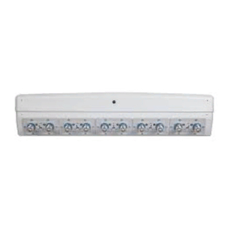
antenna from the rear). There are 10 connectors to the antenna, one for each beam of the antenna
at a polarization of +45° and one for each beam at a polarization of -45°.
The pairs of connectors for each beam direction are shown in Figure 7.
The labelling metioned here are not applyable for the antennas series number are,
00000001,00000002,00000003,00000004.
+40 ºBeam
pointing
Figure 7 Arrangement of connectors on the base of the antenna.
Operation of Antennas
RF Cable
Connection
+20 ºBeam
pointing
The 7-16 female connectors fitted to the antenna are designed to fit jumper
cables with a standard 7-16 RF male connector. After ensuring both mating
connectors are dry push the male connector in and tighten the connector
coupling to 23 - 28Nm (17 -21 ft.lb).
If needed or as required by local procedures a weatherproofing kit may
then be fitted to the connection.
If the RF connectors are tightened beyond the recommend torque the RF
connection to the antenna may be damaged.
For Multi-Beam Panel Antenna 5NPX1006F
0 ºBeam
-20ºBeam
pointing
-40ºBeam
pointing
pointing