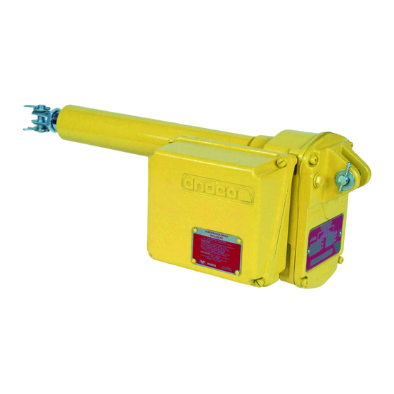
Andco Eagle Kurulum Kılavuzu - Sayfa 4
Kontrolör Andco Eagle için çevrimiçi göz atın veya pdf Kurulum Kılavuzu indirin. Andco Eagle 12 sayfaları.

5.
Remove the intermediate gear (23).
6.
Remove the woodruff key (14) and gear spacer (13)
from the drive screw.
7
.
Install a flex nut (17) 2–3 turns and tap lightly with a
soft face hammer on the end of the drive screw (4).
8.
Once the drive screw moves freely through the
bearings (12), remove the flex nut from Step 6 and
complete the removal of the drive screw/extension
rod assembly.
5.5 Drive Nut
1.
Clamp the drive nut (7) in a soft jawed vise. With a
spanner wrench in the holes of extension rod (6)
unthread the rod. The threads are Loctited, so it
may be necessary to apply heat in this area. Do not
exceed 350°F maximum surface temperature.
2.
Remove the extension rod, removed bearing assem-
bly from the end of acme screw and unscrew the
acme nut.
6.0 Reassembly
1.
To reassemble the actuator reverse the above
procedures with the following instructions.
2.
Clean the threads and apply Loctite 242 when
reassembling the drive nut (7) to the extension rod
(6) and the body tube (5) to the main housing (26).
3.
If disassembled per previous steps, discard the flex
nuts (1 and 17) and replace with new.
4.
The actuator is to be lubricated before being
returned to operation. Use acceptable lubricant
given in Table 3. The drive screw (4) is lubricated by
filling the body tube (5) with the proper amount of
lubricant per Table 2 through the hole in the main
housing (26) where the limit switch assembly (36)
drive engages the helical gear (9).
5.
After completing reassembly, mounting adjustments
can be made by threading the clevis (29) in or out of
the extension rod (6) to the suit.
Note: The thread grip is limited, make sure the clevis
is engaged by a minimum of four threads and that it
does not contact the drive screw (4) when the exten-
sion rod (6) is fully retracted.
6.
Rest the geared position limit switch before operat-
ing the actuator if the limit switch assembly has
been removed from the actuator.
6.1 High Potential Test
1.
Do not apply this test to units equipped with motor
control cards. Tests which involve putting electrical
power to units equipped with motor control cards
are covered by a separate procedure.
2.
Select the voltage setting for the appropriate motor
voltage as indicated on nameplate. Set the selected
test equipment to the selected volts.
4
3.
With the test equipment ground wire contacting
the gear case plate, contact each test point shown
on wiring diagram. The actuator shall be capable of
withstanding for one second per test point, without
breakdown, the applied voltage from Table 1.
Table 1 - HIPOT Testing Specifications
Test
Circuit
Duration/Test
Voltage
Point
12 VDC
One Second
24 VDC
One Second
120 VAC 1PH
One Second
220 VAC 1PH
One Second
220 VAC 3PH
One Second
460 VAC 3PH
One Second
575 VAC 3PH
One Second
Note: Motor power circuits are to be tested based on
the motor voltage (AC). Dielectric strength tests may be
made by applying a direct current (DC) voltage instead
of an alternative current (AC) voltage, provided that the
voltage used is 1.414 times the values specified above.
See wiring diagram for test points.
6.2 Ground Continuity
1.
Verify continuity between actuator ground lug and
ground.
6.3 Functional Test
1.
Electrically energize the actuator.
2.
Drive the actuator over the full range of motion.
7.0 Lubrication Instructions
Every Eagle linear actuator has been lubricated for life
at the factory and should not require further lubrication
if operated at published duty cycle, rated thrust and in
appropriate environmental conditions. However, if the
unit is disassembled, it should be cleaned and lubricated
as given in step 4 of Section 6.0. The amount of lubricant
in each actuator depends on the stroke of the actuator
as shown in Table 2.
Table 2 - Actuator lubricant amount per stroke length
Stroke
Actuator Lubricant Amount
(Inches)
6
12
18
24
30
36
Max
Test Voltage
Acceptable
(AC) setting
Leakage
1000 Volts
10.33 mA
1000 Volts
10.33 mA
1200 Volts
10.33 mA
1200 Volts
10.33 mA
1200 Volts
10.33 mA
1200 Volts
10.33 mA
1200 Volts
10.33 mA
(Body Tube)
(Pounds)
.22
.36
.51
.66
.81
.96
