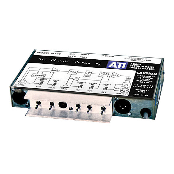
ATI Technologies M100 Kullanım ve Bakım Kılavuzu - Sayfa 4
Amplifikatör ATI Technologies M100 için çevrimiçi göz atın veya pdf Kullanım ve Bakım Kılavuzu indirin. ATI Technologies M100 8 sayfaları. Ati ultimike m100 microphone amplifier operating and maintenance manual
Ayrıca ATI Technologies M100 için: Kullanım ve Bakım Kılavuzu (9 sayfalar)

Different types of attachment plugs or line cords may be required for connection to
alternate supply voltages.
INSTALLATION
MOUNTING
The M100 can mount to any flat surface with the included angle brackets, which should
be mounted to opposite small faces of the M100 by the cover screws. The M100 can be
rack mounted either singly or in pairs in only 1-¾" using accessory Front Panel Kit, P/N
20273-501.
GROUNDING
The M100 includes an output transformer, a beaded, bypassed and clipped input network,
a triple protected AC input, a double ground plane PC board and a well shielded magnetic
enclosure. However, in a difficult broadcast application, RF levels may require a better
ground path for the RF bypass networks than can be provided by the third wire AC
ground. In difficult cases, a separate low inductance studio ground bus tied to the chassis
may be necessary.
The power line ground could cause a loop with a separate studio ground. If you are sure
your studio ground will provide adequate protection to your personnel in case of an
accidental AC short to the chassis, a 3-to-2 adapter can be used to isolate the power line
ground. We strongly recommend that the adapter be removed and the power line ground
be reconnected prior to any service work requiring removal of the studio ground from the
chassis.
INPUT AND OUTPUT CABLES
The female XLR type input connector is wired conventionally with pin 2 HI and pin 1
and the connector housing grounded. +48 VDC phantom power is applied to both pins 2
and 3 with reference to ground on pin 1.
The male XLR type output cable connector is wired with pin 2 HI, pin 3 LO and pin 1
floating. The connector housing is grounded to the chassis. Pin 1 is left ungrounded to
prevent large loop currents from circulating through the cable shield if inadvertently
grounded at both ends. The shield should be grounded at the receiving end of the signal.
If it is absolutely necessary to ground pin 1, ground lift jumper W4 can be inserted into
the circuit board.
Audio Technologies Inc. | 154 Cooper Road #902 | West Berlin, NJ 08091 | Voice 856-719-9900 | Fax 856-719-9903 | www.
audio.com
