Advanced Measurement Technology ORTEC A-576 A-PAD Kullanım ve Servis Kılavuzu - Sayfa 7
Amplifikatör Advanced Measurement Technology ORTEC A-576 A-PAD için çevrimiçi göz atın veya pdf Kullanım ve Servis Kılavuzu indirin. Advanced Measurement Technology ORTEC A-576 A-PAD 11 sayfaları. Preamplifier, amplifier, discriminator with bias supply

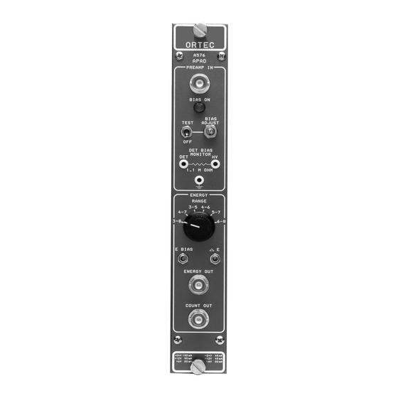
COUNT Front-panel BNC connector provides a NIM-
standard positive pulse for gross alpha counting or
routing. Pulse width 3.5 µs for any event with energy
6
>2.5 MeV. Z = 50
; dc-coupled.
0
DET BIAS MONITOR Voltage can be monitored
between front-panel test point (labeled HV) and
ground. Detector current can be monitored across
resistor between front-panel test points DET and HV.
The current is 1 µA per volt when using a voltmeter
6
with 10-M
input impedance.
3.1. JUMPER SETTINGS
Six plug-in jumpers on the printed circuit board (PWB)
must be set for compatible operation. These jumpers
are accessible when the side panel is removed from
the instrument chassis. Five of the jumpers are used
to select either positive or negative detector voltage
polarity and the corresponding correct amplifier
polarity. Negative bias is required for ORTEC
Ruggedized detectors; positive for conventional
surface-barrier or ion-implanted detectors. These five
internal jumpers need to be changed only when a
Ruggedized detector is replaced with one of the other
detectors or vice versa. The sixth jumper is used to
set the pulse generator equivalent energy (see TEST
PULSE).
POLARITY When polarity selection needs to be
changed:
a. Remove the A-PAD module from the bin and
power supply.
b. Remove the side panel from the right side of the
module as viewed from the front panel.
c. Note the locations of all five jumpers on the
components side of the PWB (Fig. 2). The "+" and
3
2.5. ELECTRICAL AND MECHANICAL
POWER REQUIRED +12 V, 90 mA; -12 V, 45 mA;
+24 V, 100 mA; -24 V, 45 mA.
WEIGHT
Net 0.9 kg (2.0 lb).
Shipping 2.25 kg (5.0 lb).
DIMENSIONS NIM-standard single-width module
3.43 × 22.13 cm (1.35 × 8.714 in.) per TID-20893
(Rev).
3. INSTALLATION
Fig. 2. Jumper Locations for Setting Polarity on the PWB.
d. Place all five of these jumpers at "
Ruggedized detector, or at "+" for a conventional
surface barrier detector or silicon dioxide-
passivated, ion-implanted detector.
" orientation for each of the jumpers is
"
etched on the PWB.
" for a
