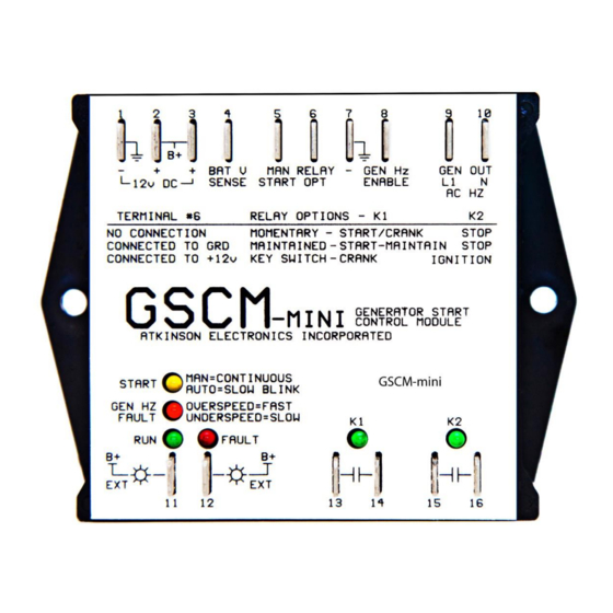
Atkinson Electronics GSCM-mini-P Manuel - Sayfa 3
Kontrol Ünitesi Atkinson Electronics GSCM-mini-P için çevrimiçi göz atın veya pdf Manuel indirin. Atkinson Electronics GSCM-mini-P 18 sayfaları. Generator start control module

Three Modes of Relay Operation
There are 3 program options based on the generator
make for the GSCM-mini-P's two relay contacts to be
: Champion, Cummins/Onan &
configured
Westinghouse, and Duramax
This is accomplished with an
optional jumper on terminal 6.
Option #1 Champion's inverter generator:
Terminal 6 has no connection. The GSCM-mini-P
program is configured for a 1 second pulse (K1) to
wake up the generator's ECU, and a second 1 second
pulse (K1) to begin the generators start sequence. On
shutdown, the K2 relay produces a 1 second pulse for
the ECU to stop the generator. See Section 1 for
operation description.
Option #2 Cummins/Onan & Westinghouse
generators:
Terminal 6 connected to B+ (12VDC).
The GSCM-mini-P program configures K2 for main-
tained operation and K1 for 1 second start/stop pulse
operation. The K2 contact wires in parallel with the
power switch and K1 wires in parallel with the push
button switch. A SPDT relay is used to open the
connection between ground and the Ignition coil. See
Section 2 for operation description.
Option #3 Duramax generator:
connected to ground. The GSCM-mini-P program is
similar to option #2, instead of 3 start attempts per 1
second start pulse, It is configured for Duramax's
single 1 to 5 second start pulse, if the generator fails
to start during the 5 second start pulse, the mini-P
generates another start pulse, is will attempt up to 6
times to start the generator before going into a fault.
See section 3 for operation description.
If adjustability is required then
refer to the GSCM full function
control module.
www.atkinsonelectronics.com
Circuit Board Division
800.261.3602
LED Indication Description
The GSCM-mini-P has six indication LEDs.
The Start LED blinks every 5 seconds to indicate it is ready for
a start signal. The LED will blink every 2.5 seconds to indicate
its running in auto start mode. On continuously indicates
running in manual start mode.
The Generator Hz LED blinks to indicate over/under Hz fault
and start failure due to maximum crank attempted. A slow
blink indicates an under Hz condition while a fast blink
indicates an over Hz condition. On continuously indicates AC
present in a non-run condition. A double blink indicates a
start failure condition. Four blinks indicates generator shut
down due to its own fault condition or lack of fuel.
The Run LED, On continuously indicates a valid run signal
from the generator.
The Fault LED, On indicates a fault condition has occurred
and GSCM-mini is in lockout and must be reset.
The K1 and K2 LEDs indicate the relay status.
Operational Thresholds
GSCM-mini-P' fixed operational thresholds:
Start Pulse:
AC Crank Disconnect:
DC Crank Disconnect
Under Speed Shutdown:
Over Speed Shutdown:
Terminal 6 is
Max Auto Start Run time:
Manual Start Run Time:
Auto Start/Stop Thresholds: Start
Relay Configuration:
(Terminal 6)
Fault Detection:
Start failure (Depends on option)
Over Hz condition (10 seconds)
Under Hz condition (10 seconds)
Max run time auto restart within 30m
Generator stops due to its own fault condition
3
1 to 5 seconds
45Hz
Voltage greater than 9VDC
55Hz
65Hz
6 Hours
Indefinitely
12V system
11.5V
24V system
23.0V 27.6V
48V system
46.0V
Open input = Momentary Crank
Grounded input = Maintained Crank
B+ (12VDC) input = Ignition & Crank
Stop
13.8V
Standard
Auto selects
55.2V
Auto selects
Revised 02/21
