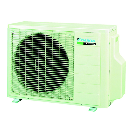
Daikin 2AMX50G3V1B Kurulum Kılavuzu - Sayfa 11
Isı Pompası Daikin 2AMX50G3V1B için çevrimiçi göz atın veya pdf Kurulum Kılavuzu indirin. Daikin 2AMX50G3V1B 20 sayfaları. Split series

Refrigerant Piping Work
4.
Purging air and checking gas leakage
WARNING
• Do not mix any substance other than the specified refrigerant (R410A) into the refrigeration cycle.
• When refrigerant gas leaks occur, ventilate the room as soon and as much as possible.
• R410A, as well as other refrigerants, should always be recovered and never be released directly into the environment.
• Be sure to check for gas leaks.
• When piping work is completed, it is necessary to purge the air and check for gas leakage.
• Be sure to perform vacuum pumping for all the rooms at the same time.
• Be sure to use the special tools for the R410A (gauge manifold, charge hose, vacuum pump, vacuum pump adapter, etc.).
• Use a hexagonal wrench (4mm) to operate the stop valve rod.
• All refrigerant pipe joints should be tightened with a torque wrench at the specified tightening torque.
1) Connect the charge hose protrusions (the side for pushing the pin) for low pressure and high pressure on the gauge manifold to
the gas stop valve service port for rooms A and B.
2) Fully open gauge manifold's low-pressure valve (Lo) and high-pressure valve (Hi).
3) Apply vacuum pumping for 20 minutes or longer. Check that the compound pressure gauge reads –0.1MPa (–76cmHg).
4) After checking the vacuum, close the low pressure and high pressure valves on the gauge manifold and stop the vacuum
pump. (Leave as is for 4-5 minutes and make sure the coupling meter needle does not go back. ) If it does go back, this may
indicate the presence of moisture or leaking from connecting parts.
After inspecting all the connection and loosening then retightening the nuts, repeat steps 2) → 3) → 4).
5) Remove the valve caps on the liquid and gas stop valves at the pipes for rooms A and B.
6) Open the valve rods on the liquid stop valves for rooms A and B by turning them 90° counterclockwise using a hex wrench.
Close them 5 seconds later and check for gas leaks.
After checking for gas leaks, check the areas around flares on the indoor unit, and the areas around flares and valve rods on
the outdoor unit by applying soapy water.
Wipe down thoroughly after the check is complete.
7) Remove the charge hose from the gas stop valve service ports at the pipes for rooms A and B and completely open the liquid
and gas stop valves at the pipes for rooms A and B.
(Stop the valve rods as far as they go and do not attempt to turn them any further.)
8) Use a torque wrench to tighten the valve caps and service port caps on the liquid and gas stop valves at the pipes for rooms A
and B to the designated torque.
7
Compound
gauge
Gauge manifold
Low-pressure valve
High-pressure valve
Charge hose
Vacuum pump adapter
Vacuum pump
Valve cap
Room A liquid
stop valve
Room A gas
stop valve
Room B liquid
stop valve
Room B gas
stop valve
Service port
■English
