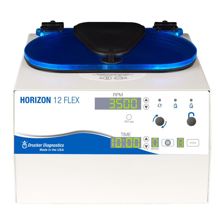
Drucker Diagnostics Horizon 12 Flex Servis Kılavuzu - Sayfa 6
Laboratuvar Ekipmanları Drucker Diagnostics Horizon 12 Flex için çevrimiçi göz atın veya pdf Servis Kılavuzu indirin. Drucker Diagnostics Horizon 12 Flex 12 sayfaları.
Ayrıca Drucker Diagnostics Horizon 12 Flex için: Operatör El Kitabı (18 sayfalar)

•
Important: When verifying rotor speed, make certain that all carriers are installed
in the rotor.
•
No calibration adjustment of speed can be made, only a verification of rotor speed.
7.6. Removing the Cabinet (Upper Housing)
•
There are eight screws that fasten the centrifuge cabinet to the base.
•
Begin by unplugging the centrifuge.
•
Use a 3/32 hex key to remove the cabinet screws (three on left and right sides, two
in the rear)
•
The cabinet control panel is attached to the base internally with cable harnesses.
Be careful not to stress the cables when removing the cabinet.
•
Stand directly in front of the centrifuge and lift the cabinet straight up and off the
base, setting it down on its right side.
•
Gently remove the power supply and motor harnesses from the PCB.
7.7. Replacing the Lid Lock Assembly
•
The lid tray assembly is accessible once the cabinet has been removed.
•
Gently remove the lid tray wire harness from the PCB.
•
The lid tray assembly is held in place with two #6 Nylok nuts. Use a 5/16" nut driver
to remove the nuts. The tray will slide off the threaded studs.
•
To install the lid tray, slide it onto the studs, and secure it with two #6 Nylok nuts,
hand tight.
•
Complete the installation by gently plugging the wire harness into the PCB header
'J4'. The header and connector are keyed for proper orientation.
7.8. Replacing the PCB
•
The PCB is accessible once the cabinet has been removed. Make certain that all
wire harnesses have been disconnected. Use standard precautions for handling
static sensitive components.
•
The PCB is held in place with six #6 Nylok nuts and plastic insulator washers. Use a
5/16" nut driver to remove the nuts. The PCB and washers are now free to slide off
the threaded studs.
•
Beneath the PCB are six plastic standoffs. If they are crushed, replace them before
reassembly.
•
To install the PCB, make certain that six plastic standoffs are present on the control
panel studs.
•
Slide the board onto the studs
•
Install six plastic washers onto the studs securing the circuit card.
•
The six nuts should be tightened only until the buttons on the control panel click
when pressed – do not over tighten. Each nut sets the height of a separate control
panel button. Too low, and they cannot be actuated, too high and they jam against
DRUCKER DIAGNOSTICS
HORIZON 12 FLEX SERVICE MANUAL
SM028
REV A
6
