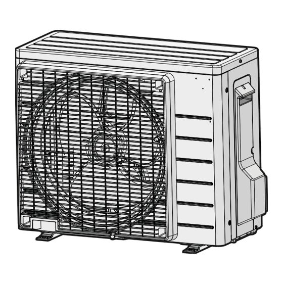
CHOOSING A SITE
• Before choosing the installation site, obtain user approval.
Indoor unit
Caution
• When moving the unit during or after unpacking, make sure to lift it by holding its lifting lugs. Do not exert any pressure on
other parts, especially the refrigerant piping, drain piping and flange parts.
Wear protective gears (gloves and so on) when installing the unit.
• If you think the humidity inside the ceiling might exceed 30°C and RH80%, reinforce the insulation on the unit body.
Use glass wool or polyethylene foam as insulation so that the thickness is more than 10mm and fits inside the ceiling opening.
• Optimum air distribution is ensured.
• The air passage is not blocked.
• Condensate can drain properly.
• The ceiling is strong enough to bear the weight of the indoor unit.
• A false ceiling does not seem to be at an incline.
• Sufficient clearance for maintenance and servicing is ensured.
• Piping between the indoor and outdoor units is within the allowable limits.
(Refer to the installation manual for the outdoor unit.)
• The indoor unit, outdoor unit, power supply wiring and transmission wiring is at least
1 meter away from televisions and radios. This prevents image interference and
noise in electrical appliances. (Noise may be generated depending on the conditions
under which the electric wave is generated, even if a one-meter allowance is
maintained.)
• The equipment is not intended for use in a potentially explosive atmosphere.
Use suspension bolts to install the unit. Check whether or not the ceiling is
strong enough to support the weight of the unit. If there is a risk that the
ceiling is not strong enough, reinforce the ceiling before installing the unit.
Select the *H dimension such that a downward slope of at least 1/100 is ensured as indicated in "DRAIN PIPING WORK".
• To avoid contact with the fan, one of the following precaution actions must be taken:
- Install the unit as high as possible at a minimum bottom height of 2.7 m.
- Install the unit as high as possible at a minimum bottom height of 2.5 m in case the fan is externally screened by parts
which can be removed without the aid of tools (e.g. false sealing, grill ... ).
- Install the unit with ducting and grill which can only be removed with the aid of tooling. It shall be installed so that it
gives adequate protection against touching the fan. If a maintenance panel exists in the ducting, it shall only be
possible to remove the panel by the aid of tooling to avoid contact with the fan. The protection shall be according to
relevant European and local legislation. There are no restrictions concerning the installation height.
Select the signal receiver mounting location according to the following conditions:
• Install the signal receiver, which has a built-in temperature sensor, near the intake vent where
there is convection of air and it can get an accurate reading of the room's temperature. If the
intake vent is in another room or the unit cannot be installed near the intake vent for any
other reason, install it 1.5m above the floor on a wall where there is convection.
• In order to get an accurate reading of the room's temperature, install the
signal receiver in a location where it is not exposed directly to cold or hot air
from the air discharge grille or to direct sunlight.
• Since the receiver has a built-in light receptor to receive signals from the wireless remote
controller, do not mount it in a location where the signal may be blocked by a curtain, etc.
Caution
If the signal receiver is not installed in a location where there is convection of air, it may be unable to get an accurate reading of the room's temperature.
Wireless remote controller
• Turn on all the fluorescent lamps in the room, if any, and find the site where remote controller signals are properly received
by the indoor unit (within 4 metres).
Outdoor unit
• For outdoor unit installation, see the installation manual supplied with the outdoor unit.
English
300 or
more
Control box
Maintenance
space
20 or more
Ceiling
Floor surface
(length : mm)
Air discharge grille:
Wooden or plastic grille is recommended
because condensation may occur depending
on humidity conditions.
3

