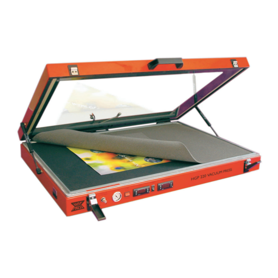
Drytac HOT PRESS HGP360 Kullanıcı Kılavuzu - Sayfa 4
Elektrikli Alet Drytac HOT PRESS HGP360 için çevrimiçi göz atın veya pdf Kullanıcı Kılavuzu indirin. Drytac HOT PRESS HGP360 19 sayfaları. Heated glass top vacuum press
Ayrıca Drytac HOT PRESS HGP360 için: Operatör El Kitabı (19 sayfalar)

HOT PRESS USERS MANUAL
S
U
Y
ETTING
P
OUR
Equipment Location: The smaller vacuum press models
such as the HGP220 and HGP260 may be used on a
table or countertop, provided that it is able to support
the weight of the equipment. The larger models should
be used with a fl oor stand due to their size and weight.
The ideal working height of the press will vary depending
on the operator. We suggest a height of 28 to 31 inches
(700 to 790 mm). It is critical that the lid of the press is
able to open fully. Please be absolutely sure that nothing
interferes with this!
For proper operation, it is very important that the press
be fl at and level. The best way to verify this is to use a
carpenter's (bubble) level. If one corner of the unit is at a
different height from the others, it may be diffi cult to achieve
a proper vacuum. For best results, we recommend that
the press be located away from air conditioning vents,
fans and other sources of moving air.
Unpacking: Carefully inspect the vacuum press for possible shipping
damage. If any is discovered, please contact our Customer Service
Department immediately. If you are using a fl oor stand, unpack and
assemble it using the instructions provided. Remove the vacuum press
from the shipping carton and place it on the stand or table. Leave room
to make connections to the rear of the unit.
Unpack and remove the vacuum pump from its box. The pump
should be placed on or near the fl oor. There are suction cups
on the bottom of the pump to help keep it in place, since the
pump vibrates during operation. The pump will become warm
during extended usage. If the equipment is going to be used in a
high-volume production environment, please allow for adequate
ventilation of the area where the pump is located.
Stand Assembly (Model HPG560 Only)
Loosely fi t the four tie bars to the ends of the stand (Illustration
4B), using the 16 M10 x 50 bolts, 32 x M10 plain washers and 16
M10 nuts. Tighten all nuts and bolts. Move stand into fi nal position
and ensure that it is level by using the leveling spacers. The stand
may be leveled by supporting the low corner of the stand on the
tie bar and removing the wheel. The leveling spacers can then
be inserted between the stand and the wheel assembly and the
wheel assembly re-bolted to the stand. Lower the stand back to
the ground and re-check to make sure it is level.
Mount The Press Onto the Stand
(Model HPG560 Only)
Remove the divider panels from the crate. Remove the screws
from the side pieces of crate. Remove protective packaging from
the press. HOLDING THE FRONT AND REAR OF THE PRESS
ONLY AND NOT WITHIN 75 mm OR 3 INCHES OF THE ENDS, lift the
press from the crate onto the stand. Align the press with the ends of the
N
V
P
EW
ACCUM
RESS
Illustration 4A: Vacuum press mounted
on stand.
Illustration 4B: Stand assembly
Illustration 4C: Stand assembly - front
view with wheels.
4
