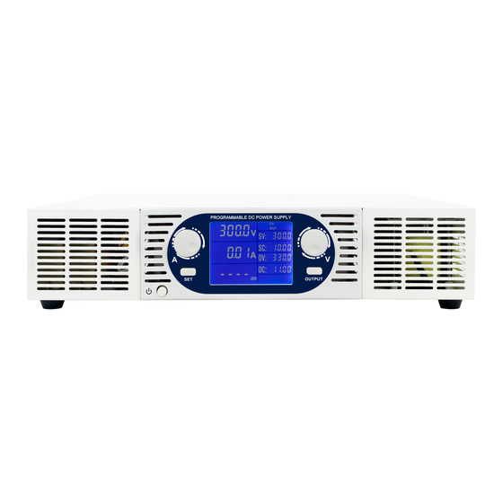
DSC ELECTRONICS DP-D Series Kullanıcı Kılavuzu - Sayfa 8
Güç Kaynağı DSC ELECTRONICS DP-D Series için çevrimiçi göz atın veya pdf Kullanıcı Kılavuzu indirin. DSC ELECTRONICS DP-D Series 14 sayfaları. High power laboratory power supplies

DP-D Series User's Manual
Version 08.01.2019
To switch between the working modes, press the first arrow key (up/down) from the right while holding "set / lock".
a). Setting the T1 / T2 Time
Use the arrow keys below the time values to increase / decrease them.
b). Resetting the timer
Set the toggle switch to the "STOP" position and press "Reset" to reset the timer.
c). Lock
To lock the control panel, hold down "Lock" while pressing the last arrow (left).
5.8 Optional: External „Output ON/OFF" Control & Interlock
Input for controlling the status of the output of the laboratory power supply (on / off), switchable as "Interlock" or
external control. This input is configured as a two pin connection, a „true" state is triggered by shorting the two pins
and a „false" state is triggered by removing any connection between the two pins of the input.
This option can be configured as either an interlock input, which disables the output of the power supply if the state is
false, or as an external output status control which enables or disables the output of the power supply depending on
the control signal state (true = on/false = off) if the „Output On/Off" switch of the power supply is always in the ON
position.
5.9 Optional: RS485 / RS232 / USB
DP-D series devices can be equipped with an RS485 connection to read/write output values in real time. Optionally the
device can be shipped with a RS485 → RS232 adapter, or with both, a RS485 → RS232 and RS232 → USB adapter.
(Please see communication protocol at the end of this manual)
5.10 Optional: Analog Control Ports
The DP-D series devices can be equipped with analog connections to read / write output values. The analog
connections can be accessed through the D-SUB connection on the rear side of the device. The pin-out is as follows:
Pin1: GND
Pin2: Voltage External Control +
Pin3: Current External Control +
Pin4: Power External Control +
Pin5: Voltage Feedback +
Pin6: Current Feedback +
Pin7: Power Feedback +
Pin8: External Output ON/OFF & Interlock
Pin9: (Reserved for custom options)
5.11 Optional: Adjustable Voltage Limit (OVP)
Devices of the DP-D series can optionally be equipped with an adjustable voltage limit, which can be addressed via the
front panel as well as via one of the digital interfaces (optional). If a voltage limit is set, a higher output voltage can
not be set either via the front panel nor via external interfaces.
DSC-Electronics Germany • Georgstraße 36 • 53111 Bonn
DSC-Electronics Germany • Georgstraße 36 • 53111 Bonn
