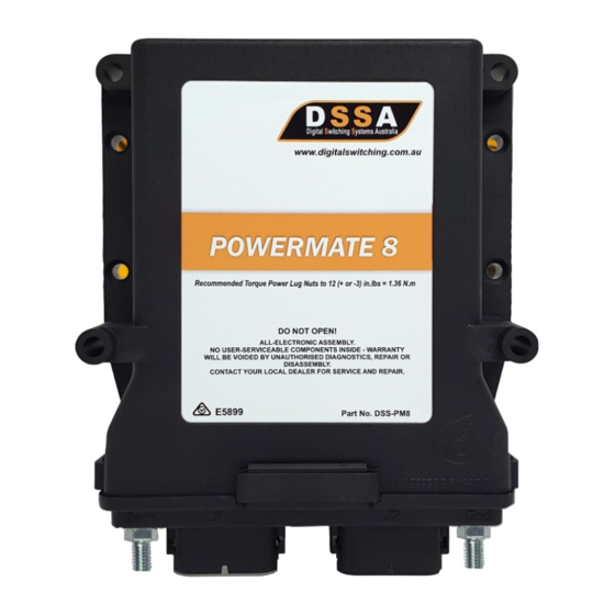
DSSA POWERMATE 8 Manuel - Sayfa 5
Taşınabilir Jeneratör DSSA POWERMATE 8 için çevrimiçi göz atın veya pdf Manuel indirin. DSSA POWERMATE 8 11 sayfaları.

DETAILED DESCRIPTION
DETAILED DESCRIPTION
MOSFET OUTPUT
MOSFET OUTPUT
PowerMate 8 has 8 MOSFET Outputs which are rated at 20 Ampere each maximum. All outputs can ONLY be
Switched to Battery. Each Output is double protected by hardware and software, i.e.
PowerMate 8 can shut down the MOSFET in case of Over-Current and
In case of software exception, the fuse will be blown to protect the circuit from further damages.
BINARY INPUT
BINARY INPUT
PowerMate 8 has 8 Binary Inputs which are capable of reading Digital High/Low Input. Each Binary Input can be
configured as Switch to Ground (STG)/Switch to Battery (STB) and High/Low Active independently:
1.
STG Active Input examples: - Park Brake, Door Switch, Locker Doors etc.
STB Active Input examples: - Ignition, PTO, High Beam etc.
2.
ALL Binary Inputs by default are configured as STB Active Inputs.
OMNIBUS INTERFACE
OMNIBUS INTERFACE
PowerMate 8 has one RS-485 channel. It can communicate with other PowerMate Series Digital Switching modules
and Keypads within the system network using the OmniBus Interface.
PowerMate 8 is default configured to communicate at 9600 bps (9600, 8-N-1).
The user can retrieve system status such as output and input pin conditions, current status, analog input
values as well as battery status.
CAN INTERFACE
CAN INTERFACE
PowerMate 8 has one CAN channel. It can communicate with other PowerMate Series Digital Switching Systems
using CAN Interface.
PowerMate 8 is default configured to communicate at 250 kbps.
PowerMate 8 supports CAN protocols such as J1939, CANOpen, CANStandard etc.
Common Status that the PowerMate Series Digital Switching Systems would be able to obtain from the
CANbus include:
Vehicle Speed
Engine Revolution Per Minute
Gear Position
Further customisation is possible to suit specific client requirements.
www.digitalswitching.com.au
Page 5: DSS-PM8_SpecSheet_V.0920_A
