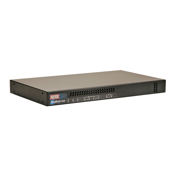
ATTO Technology FibreBridge 6500 Başlangıç Kılavuzu
Depolama ATTO Technology FibreBridge 6500 için çevrimiçi göz atın veya pdf Başlangıç Kılavuzu indirin. ATTO Technology FibreBridge 6500 2 sayfaları.

ATTO Technology, Inc.
155 CrossPoint Parkway
Amherst, New York 14068 USA
www.attotech.com
Tel
(716) 691-1999
Fax
(716) 691-9353
Sales support:
Technical support: Monday -- Friday, 8am-6pm EST
[email protected] (716)691-1999 ext. 242
© 2015 ATTO Technology, Inc. All rights reserved. All brand or product names are trademarks of their respective holders.
No part of this document may be reproduced in any form or by any means without the express written permission of ATTO
Technology, Inc.
06/2015
Thank you for purchasing an ATTO FibreBridge. This guide gives you the basics for installing
and configuring your FibreBridge. For more information, refer to the FibreBridge Installation
and Operation Manual
Examine the contents of your FibreBridge
packing box. If any of the items listed below
are missing, contact your ATTO
representative.
• The FibreBridge. Note the serial number of
your FibreBridge unit:
________________________
• Power cord(s)
• "L" brackets for mounting in a 19" rack
• Ethernet cable
• RS 232 cable
1 Install the FibreBridge
Note
Please visit the download section of www.attotech.com for
Firmware, Installation and Operation Manual,
QuickNAV™ IP discovery program and system drivers
1.1 Place the FibreBridge on a stable flat
surface, install it into a standard rack or
into your device.If installing the
FibreBridge 6500 into a rack, see Exhibit
1 and follow these instructions:
a. Attach "L" brackets so that the front
side with the LEDs face front and the
connector side is at the back.
b. Install the FibreBridge horizontally
within the rack so it does not reduce the
air flow within the rack.
PRMA-0422-000MD
FibreBridge™ 6500
Getting Started Guide
1.2 Connect and power up Fibre Channel
devices from your SAN to the FibreBridge
using SFPs and multimode fiber optic
cables for the Fibre Channel ports. Keep
cable lengths as short as possible to
ensure the highest signal quality and
performance. Refer to Cabling in the
FibreBridge Installation and Operation
Manual.
1.3 Connect and power up SAS/SATA target
devices. Refer to Cabling in the
FibreBridge Installation and Operation
Manual.
1.4 Connect the Ethernet port to your
network.
1.5 Connect power:
a. Connect the AC power cord(s) from
the FibreBridge to the proper AC
source outlet and turn on the power
using the power switch on each
receptacle.
Note
The power source must be connected to a protective
earth ground and comply with local electrical codes.
Improper grounding may result in an electrical shock
or damage to the unit.
If you are using a rack:
a. Properly ground the FibreBridge to the
rack equipment. The earth ground
connection must be maintained.
