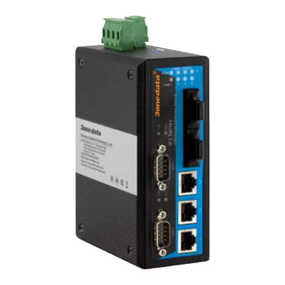
3onedata IES615-2D Series Kullanıcı Kılavuzu - Sayfa 2
Anahtar 3onedata IES615-2D Series için çevrimiçi göz atın veya pdf Kullanıcı Kılavuzu indirin. 3onedata IES615-2D Series 5 sayfaları. Managed industrial ethernet switch
Ayrıca 3onedata IES615-2D Series için: Hızlı Kurulum Kılavuzu (3 sayfalar)

1. Power input terminal block
2. Ground screw
3. 2-pin terminal block for relay output
4. DIP switches for default factory
5. Screw holes for Wall Mounting Kit
6. DIN-Rail mounting kit
7. System running LED
8. Link/ACT LEDs
9. Power indicator (PWR1, PWE2)
10. Serial port transmits and receives data LED
11. RS-232 serial port (DB9M)
12. 10Base-T /100Base-TX Ethernet port
13. 100Base-FX fiber port
14. RS-485/422 serial port (5 bits terminal block)
Power supply input
The switch have redundant power input, provides one terminal
block (4 bits) for PWR1 and PWR2 input. The redundant power
can be used single and used two self-governed power to supply to
the system, PWR1 and PWR2 input at the same time, when
neither of
these two power fails, the other power acts as a
backup, and automatically supplies power needs, ensure running
Ethernet reassuring. Voltage input range is 12 48VDC (terminal
block defined as: V1- V1+ V2- V2+).
Dimension
The series of switches are the same size, and the number of the
Ethernet interface is different. Unit (mm)
DIP Switch
Top panel provided 4 bits DIP switch to do function configure
OFF is default factory ,1 and 2 keep for future function. 3 is
AT mode. 4 is recovery default factory. Please power off and
power on when you change the status of DIP switch.
Relay connection
The relay owns two contacts of the terminal block on the top
panel of the Switch series. It is used to detect both power failure
and port failure. The open circuit state in normal non alarm state,
when there is any alarm information to the closed state. The relay
- 2 -
can external alarm lights or alarm buzzer or external switch signal
acquisition device in order to timely notify operators when an
alarm occurs.
Console port
This series product provided 1pcs procedure test port based in
serial port. It adopts RJ45 interface, located in top panel, can
configure the CLI command through RJ45 to DB9 female cable.
Communication connector
10/100BaseT(X) Ethernet port
The pinout define of RJ45 port display as below, connect by UTP
or STP. The connect distance is no more than 100m. 100Mbps is
used 120 of UTP 5, 10Mbps is used 120 of UTP 3 ,4, 5.
RJ 45 port support automatic MDI/MDI-X operation. can
connect the PC, Server, Converter and HUB .Pin 1,2,3,6
Corresponding connection in MDI. 1→3, 2→6, 3→1, 6→2 are
used as cross wiring in the MDI-X port of Converter and HUB.
10Base-T/100Base-TX are used in MDI/MDI-X, the define of Pin
in the table as below.
1
8
