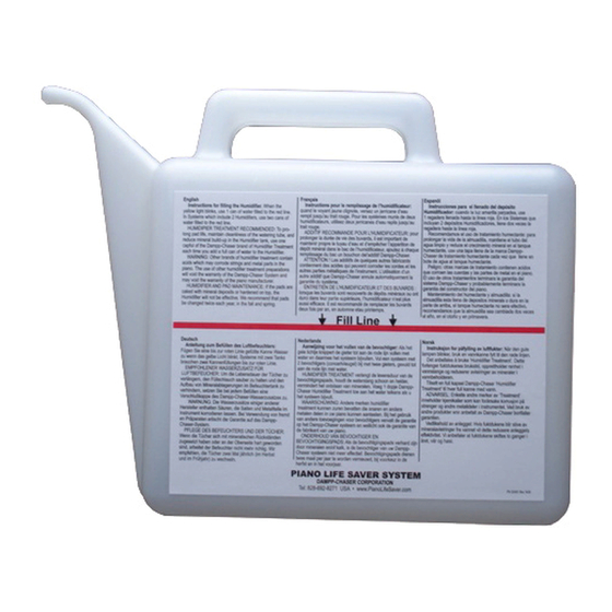
DAMPP-CHASER Piano Life Saver System Kurulum Talimatları Kılavuzu - Sayfa 7
Müzik Enstrümanları İçin Aksesuarlar DAMPP-CHASER Piano Life Saver System için çevrimiçi göz atın veya pdf Kurulum Talimatları Kılavuzu indirin. DAMPP-CHASER Piano Life Saver System 8 sayfaları. Backside vertical 8-part system which includes two humidifiers
Ayrıca DAMPP-CHASER Piano Life Saver System için: Kurulum Talimatları (4 sayfalar), Kurulum Talimatları Kılavuzu (9 sayfalar), Bakım ve Onarım Talimatları (2 sayfalar)

Connect the three Dehumidifiers to the brown extension cord.
Run the cut end of the brown extension through the same hole
in the bottom board as the white extension cord. Connect a
Super Plug to the cut end of the brown DEHUMIDIFIER cord in
the inside of the piano (Figure 11). Plug the brown extension
cord Super Plug into the DEHUMIDIFIER outlet on the
Humidistat (Figure 12, page 6).
STEP 6. ROUTING THE HUMIDISTAT
POWER CORD
If you have not already done so, run the Humidistat power cord
up beside the action and out the lid (Figure 15). Alternatively,
you may route the main power cord for the Humidistat out of the
piano through the hole previously drilled in the piano bottom
board. To provide strain relief for the cord, knot it and secure
the knot to an appropriate wood area with one of the 1/4-inch
clamps and a 1/2-inch screw.
After you have completed installation of the System, plug the
Humidistat into a non-switchable wall outlet.
Notice the Fused Plug on the Humidistat Power Cord in Figure
16. In the event of damage to the cord, or a direct lightning
FIGURE 15
Two-light
panel
FIGURE 17
ongue-latch and prongs
T
insert in openings
For several years we have included fused
plugs on all Systems which protect pianos
in the United Kingdom and "blown" plug
fuses are a rare occurrence.
SB
light
strike, the fuse in the plug will "blow out" and prevent the flow of
electricity through the power cord, thus preventing any further
damage. The plug contains two 5-AMP, 125-Volt glass fuses. If
the green POWER light is not on, advise the piano owner to
unplug the System and inspect the cord for damage. If there is
no damage, remove the fuse from the brass clips inside the
plug and replace it with the spare fuse in the plug. If the cord is
damaged, the Humidistat should not be plugged into an
electrical outlet. Call our technical support number for
instructions, (800) 438-1524 or (828) 692-8271.
Only 5-AMP, 125-Volt , 5 mm x 20 mm, fast-acting, glass fuses
should be used in the plug. Never use a fuse with greater
amperage than 5 AMPS. These fuses are readily available at
electronics stores such as Radio Shack. In the event you cannot
find the fuses, contact Dampp-Chaser for purchasing
information.
STEP 7. LIGHT PANEL INSTALLATION
The Two-Light Panel (Figure 17) features a green light marked
POWER, to indicate the System has electrical power, and a
yellow light marked WATER, which blinks when the Humidifier
needs water. The Single-Light Cube is controlled by the Smart
Bracket (SB). The red SB light, marked PADS, will blink when
the pads need to be replaced. Connect the two-light panel and
the single-light cube together by inserting the tongue-latch and
two prongs (on the side of the single-light cube) into the
corresponding openings on the two-light panel. Insert the
metal prongs first while firmly pushing the panels together.
NOTE: the tongue-latch is slightly bent to create a snug fit
between the two panels.
To mount the light panel select two 3/4-inch screws and three
1/4-inch clamps with three 1/2-inch screws.
Run the light panel cord so that the panel is at an appropriate
location under the keybed. Usually this is at the extreme treble
end beside the leg of the piano. Use the two 3/4-inch screws to
attach the light panel under the keybed (Figure 18). Secure the
SB red light cube with the clamp and screw provided. Plug the
telephone jack from the light-panel into the Humidistat outlet
marked LIGHTS. Attach the light panel cord with three 1/4-inch
clamps and three 1/2-inch screws.
Includes (2) 5-AMP,
125-Volt, fast-acting
fuses.
FIGURE 16
7
FIGURE 18
Placement of Light Panel
