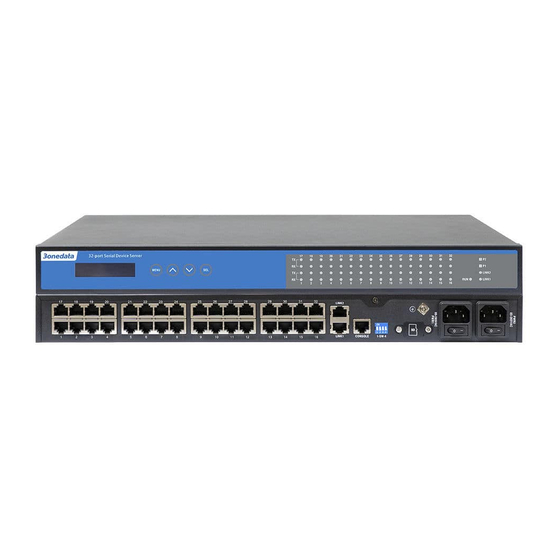
3onedata NP5100 Series Hızlı Kurulum Kılavuzu - Sayfa 2
Sunucu 3onedata NP5100 Series için çevrimiçi göz atın veya pdf Hızlı Kurulum Kılavuzu indirin. 3onedata NP5100 Series 4 sayfaları. Safe serial server
Ayrıca 3onedata NP5100 Series için: Hızlı Kurulum Kılavuzu (4 sayfalar)

18. Select/confirm button
【Mounting Dimension】
Unit: mm
Note before mounting:
Don't place or install the device in area near water or
moist, keep the relative humidity of the device surrounding
between 5%~95% without condensation.
Before power on, first confirm the supported power
supply specification to avoid over-voltage damaging the
device.
The device surface temperature is high after running;
please don't directly contact to avoid scalding.
【Rack-mounted】
This product adopts rack-mounting, mounting steps as
below:
Step 1
Select the device mounting location to ensure
enough size.
Step 2
Adopt 4 bolts to install the mounting lugs in the
device position as figure below.
Step 3
Place the device in the rack; adopt 4 bolts to fix
two sides mounting lugs in the rack.
Step 4
Check and confirm the product is mounted firmly
on the rack, mounting ends.
【Disassembling Device】
Step 1
Device power off.
Step 2
Adopt screw driver to loosen the 4 bolts fixed on
the mounting lugs in the rack.
Step 3
Shift out the device from rack, disassembling
ends.
Note before powering on:
Power ON operation: First insert the power supply
terminal block into the device power supply interface, and
then plug the power supply plug contact and power on.
Power switch "—" means power ON, "O" means
power OFF.
Power OFF operation: First, put the powers switch to
the "O" side and then disconnect the power supply. Finally
disconnect the connector between the device and the power
cord. Please notice the operation order above.
【Power Supply Connection】
AC power supply
This device provides 2 AC power supply access interfaces
which come with a switch.
Voltage range: 85~265VAC.
【Serial Port Connection】
This device provides 3IN1 serial port, which
supports RS232, RS485 and RS422 at the same
time. The interface type is RJ45 and its pin
definitions are as follows:
PIN
1
2
3
4
5
RS-232 DSR RTS GND TXD RXD DCD CTS DTR
RS-485 —
—
GND —
—
RS-422 —
R-
GND R+
—
【DIP Switch Settings】
Provide 4 pins DIP switch for function settings, where "ON"
is enable valid terminal. The device needs to be powered on
again to change the status of DIP switch.
DIP switches definition as follows:
DIP
Definition
Operation
1
Reserved
-
2
Restore
Set the DIP switch to ON, the
factory
device will root automatically
defaults
and restore to factory settings,
then turn off the DIP switch.
3
Reserved
-
4
Reserved
-
【Console Port Connection】
The series products provide 1 program debugging port
based on RS-232 serial port which can conduct device CLI
command management after connecting to PC. The
interface adopts RJ45 port, the RJ45 pin definition as
follows:
Pin No.
2
3
Definition
TXD
RXD
6
7
8
D-
—
D+
T-
—
T+
5
GND
