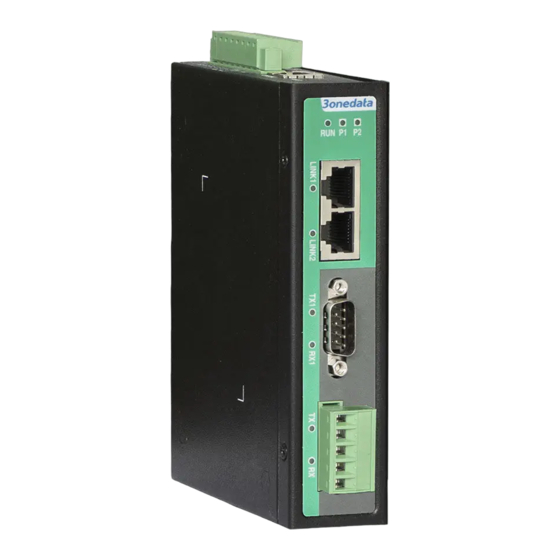
3onedata IGW1111 Series Hızlı Kurulum Kılavuzu - Sayfa 2
Ağ Geçidi 3onedata IGW1111 Series için çevrimiçi göz atın veya pdf Hızlı Kurulum Kılavuzu indirin. 3onedata IGW1111 Series 4 sayfaları. Industrial modbus gateway
Ayrıca 3onedata IGW1111 Series için: Hızlı Kurulum Kılavuzu (4 sayfalar)

【Dimension】
Unit (mm)
Model I, Model II
Model III
Note:
The mounting panel on the right of the dimension
drawing is an optional accessory, not a standard one.
Notice Before Mounting:
Don't place or install the device in area near water or
moist, keep the relative humidity of the device
surrounding between 5%~95% without condensation.
Before power on, first confirm the supported power
supply specification to avoid over-voltage damaging the
device.
The device surface temperature is high after running;
please don't directly contact to avoid scalding.
【DIN-Rail Mounting】
The product adopts 35mm standard DIN-Rail mounting which
is suitable for most industrial scenes, mounting steps as
follows:
Step 1
Check whether the DIN-Rail mounting kit that
comes with the device is installed firmly.
Step 2
Insert the bottom of DIN-Rail mounting kit (one side
with spring support) into DIN-Rail, then insert the
top into DIN-Rail.
Tips:
Insert a little to the bottom, lift upward and then insert
to the top.
Step 3
Check and confirm the product is firmly installed on
DIN-Rail, then mounting ends.
【Disassembling DIN-Rail】
Step 1
Power off device.
Step 2
After lifting the device upward slightly, first shift out
the top of DIN-Rail mounting kit, and then shift out
the bottom of DIN-Rail, disassembling ends.
Notice before power on:
Power ON operation: First insert the power supply
terminal blocks into the device power supply interface,
then plug the power supply plug contact and power on.
Power OFF operation: First, remove the power plug,
then remove the wiring section of terminal blocks.
Please pay attention to the above operation sequence.
【Power Supply Connection】
Model I, Model II, Model IV, Model V
The device provides 6 or 8-pin 5.08 pitch terminal blocks,
power supply occupies 4 pins in the left. It supports two
independent DC power supply systems, P1 and P2, which
supports nonpolarity function, that the device can work
normally after reverse connection. Voltage range: 12~48VDC.
Relay is reserved and not enabled.
【Console Port Connection】
The device provides 1 program debugging port based on
serial port. The interface adopts RJ45 port which can conduct
device CLI command management after connecting to PC.
Pin No.
2
3
Pin Definition
TXD
RXD
【Reset Button Setting】
The Model I and Model II of this series provide 1 reset button,
press the button for 4-5S then release it to restore factory
defaults.
【DIP Switch Settings】
The model III provide 4-bits DIP switch for function
setting, where "ON" is enable valid terminal. The
definitions of DIP switch are as follows:
DIP
Definition
Operation
1
Reserved
—
Set the switch to ON and
Restore Factory
2
power on again, then set it
Settings
back.
3
Reserved
—
4
Reserved
—
【Serial Port Connection】
Model III, Model VI
5
GND
