DUERR 424/LCD/20 Manuel - Sayfa 8
Kütük ayırıcı DUERR 424/LCD/20 için çevrimiçi göz atın veya pdf Manuel indirin. DUERR 424/LCD/20 16 sayfaları. Vertical log splitters
Ayrıca DUERR 424/LCD/20 için: Kullanım Kılavuzu (17 sayfalar)

I
INSTALLING THE CYLINDER AND VALVE ASSEMBLY
1.
Lower the beam to the horizontal position as
follows.
a. Remove the spring pin from the pivot latch
on the back side of the beam. Remove the >'
clevis pin.
b. Lower the beam so the tongue is inside the
pivot latch. Secure with clevis pin and spring
pin.
2.
Remove one hairpin clip from the clevis pin on
the end of the cylinder. Place the cylinder in
position on the log splitter, and secure with
clevis pin and hairpin clip just removed. See
figure 9.
3.
Remove the large hex bolt, lock washer and hex
nut on the end of the wedge assembly. Secure
the other end of the cylinder assembly with the
hardware just removed. See figure 10.
ATTACHING THE CONTROL HANDLE
The bottom of the control handle is already attach¬
ed to the valve with a cotter pin. Remove the second
cotter pin which is attached to the valve only. Place
the handle in position and secure using the second
cotter pin. See figure 10.
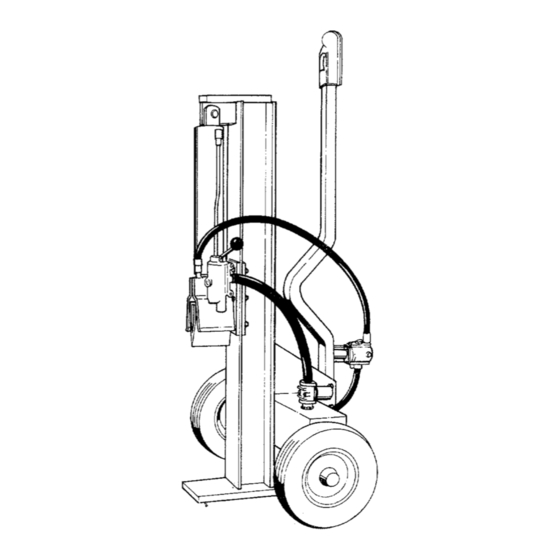
INSTALLING THE RETURN HOSE
1.
Move the beam to the operating (upright)
position by removing the spring pin and clevis
pin from the pivot latch. Place the beam upright,
and replace clevis pin and spring pin in pivot
latch for safekeeping.
2.
The return hose is 3/4" by 30'' long. Loosen the
hose clamps on each end of the hose using a
screwdriver.
3.
Attach one end of the hose to the fitting on the
hydraulic filter head (located on top of the reser¬
voir tank). Attach the other end to the fitting
beneath the valve. See figure 11.
4.
Make certain the hose is adjusted so it is
relaxed and in the proper position (do not allow
hose to twist). Place hose clamps at the base
of the fittings, and
tighten securely.
INSTALLING THE PRESSURE HOSE
1.
The pressure hose is 1/2" x 54" long. Place
Loc-tite hydraulic sealer or equivalent on the
threads on both ends of the pressure hose.
2.
Thread one end of the hose into the fitting on
top of the pump. See figure 11.
3.
Thread the other end of the hose into the
fitting on top of the valve. Adjust hose so it is
relaxed and in the proper position as shown in
figure 11. Do not allow hose to twist. Then
tighten securely.
8
