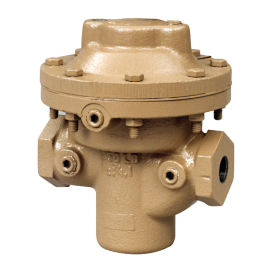
cashco DA6 Kurulum, Çalıştırma ve Bakım Kılavuzu - Sayfa 3
Kontrolör cashco DA6 için çevrimiçi göz atın veya pdf Kurulum, Çalıştırma ve Bakım Kılavuzu indirin. cashco DA6 18 sayfaları. Direct-acting, pressure loaded back pressure regulator

5. Open the outlet (downstream) block valve.
6. Slowly open the inlet (upstream) block valve to
about 25% open, observing the inlet (upstream)
pres sure gauge. The reg u la tor should be flow-
ing. Adjust the loading system pressure control
device setpoint pressure upwards until the main
valve flow is shutoff. Observe the inlet pressure
gauge to ensure not over pressurizing.
7. Continue to open inlet block valve until at least
50% open. Set loading system pressure control
device upwards to approximate 80% desired main
valve pressure level.
VI. SHUTDOWN
1. Shutoff auxiliary loading pressure source.
2. Shutoff inlet block valve.
3. Shutoff the outlet block valve.
VII.
MAINTENANCE
A. General:
1. The regulator may be serviced without re mov-
ing the regulator from pipeline. The reg u la tor
is designed with quick-change trim to simplify
maintenance.
2. Record the nameplate information to req ui si-
tion spare parts for the regulator. The in for ma-
tion should include: size, Product Code, and
Serial Number.
3. Refer to Section VIII for rec om mend ed spare
parts. Only use original equip ment parts sup-
plied by Cashco for re build ing or re pair ing
regulators.
4. Owner should refer to owner's pro ce dures for
removal, handling, cleaning and disposal of
nonreusable parts, i.e. gaskets, etc.
NOTE: On regulators originally sup plied as
"oxygen clean" – Opt-55, main te nance must
include a level of clean li ness equal to Cashco
cleaning stan dard #S-1134.
5. The Inner Trim Assembly (ITA) is re moved and
re placed in the body (23) as an as sem blage of
parts. The ITA con sists of the fol low ing parts:
IOM-DA6
8. Fully open inlet block valve.
9. Begin to slowly close the bypass valve if installed.
10. Develop system flow to a level near its expected
normal rate, and reset the regulator set point by
adjusting the loading system pressure control set
point to the desired level.
11. Reduce system flow to a minimum level and
observe pressure set point. Inlet pressure will
decrease from the set point of Step 10. The
max i mum build in inlet pressure on increasing
flow should not exceed 10%. If it does, consult
factory.
SECTION VI
4. Relieve the trapped upstream and downstream
pressure and loading pressure.
5. The regulator may now be removed from the
pipe line or disassembled for inspection and pre-
ven ta tive main te nance while in-line.
SECTION VII
Item
Dynamic Side
No.
7 ...................... All ........................Diaphragm Cap Screw
7 ...................... All ........................... Diaphragm Lock Nut
8 ...................... All .......Upper Diaphragm Pressure Plate
9 ...................... All ...................................... Diaphragm(s)
10 ..................... All ..........Lower Diaphragm Pusher Plate
13 ..................... All ....................... Piston/Guide Bearing√
14 ..................... All ......................................... Stem Seals
14.1 ............... All ................................ Upper Stem Seal
14.2 ............... All ................................Middle Stem Seal
14.3 ............... All ..............................Lower Stem Seal√
14.4 ............... All ................ Lower Pusher Plate Gasket
20 ..................... All ...........................................Valve Plug
27 ..................... All ........................... Dynamic Side Seal *
27.1 ...............CP ..................................... TFE Cap Seal
27.2 ...............CP ......................... O-ring Energizer/Seal
27.3 .............. UC .......... U-Cup Seal w/Metal Energizer
27.5 ...............PR ................................. Piston Ring Seal
27.6 ...............PR ................. Piston Ring SST Energizer
28 ..................... All ............................................ Seat Disc
29 ..................... All ............................... Seat Disc Washer
30 ..................... All ......................................Seat Disc Nut
* Possible option is with NO dynamic side seal.
√ 2-1/2" thru 4" body sizes only.
A detailed view of the dynamic side seal parts
is shown in Figure 1 on the next page.
Seal Type
Part Description
3
