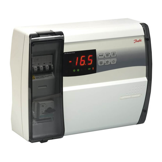
Danfoss AK-RC 111 Kullanıcı Kılavuzu - Sayfa 11
Kontrol Ünitesi Danfoss AK-RC 111 için çevrimiçi göz atın veya pdf Kullanıcı Kılavuzu indirin. Danfoss AK-RC 111 16 sayfaları. Single phase

User Guide | Optyma™ control AK-RC 111 single phase
4.11 Switching on the AK-RC
111 electronic controller
4.12 Cold/hot activation/
deactivation conditions
4.13 Manual defrosting
activation/deactivation
© Danfoss | DCS (vt) | 2020.03
In1
INP-1 input setting
In2
INP-2 input setting
bEE
Buzzer enable
mOd
Thermostat functioning mode
Password type of protection
P1
(active when PA is not equal 0)
PA
Password
(see P1 for the type of protection)
reL
Release software
After wiring the electronic controller correctly, power up at 230 V AC; the display panel will
immediately emit a beep and all the LEDs will come on simultaneously for a few seconds.
In cold mode (mOd=0), the AK-RC 111 controller activates the compressor when cold room
temperature exceeds setting + differential (r0); it deactivates the compressor when cold room
temperature is lower than the setting.
If Pump-Down function is selected (parameter AU1/AU2 = 4/-4), see chapter 4.16 for compressor
activation/deactivation conditions.
In hot mode (mOd=1), the AK-RC 111 controller activates the heat output (COMPR output) when cold
room temperature drops below setting-differential (r0); it deactivates the heat output (COMPR output)
when cold room temperature is higher than the setting.
To defrost just press the dedicated key (see section 5.2) to activate the elements relay. Defrosting will
not take place if the end-of-defrost temperature setting (d2) is lower than the temperature detected
by the evaporator sensor. Defrosting ends when the end-of-defrost temperature (d2) or maximum
defrost time (d3) is reached, or due to forced manual defrost termination (end of defrost button or
digital input).
8 = Night mode digital input
(energy saving, N.O.)
7 = Stop defrosting remotely (N.O.)
(reads rising edge of impulse)
6 = Start defrosting remotely (N.O.)
(reads rising edge of impulse)
5 = Stand-by remotely (N.O.) (In
order to indicate Stand-By
mode, the display shows 'In5'
alternating with the current
view)
4 = Pump-down pressure switch
(N.O.)
3 = Man-in-room alarm (N.O.)
2 = Compressor protection (N.O.)
1 = Door switch (N.O.)
0 = disabled
-1 = Door switch (N.C.)
-2 = Compressor protection (N.C.)
-3 = Man-in-room alarm (N.C.)
-4 = Pump-down pressure switch
(N.C.)
-5 = Stand-by remotely (N.C.) (In
order to indicate Stand-By
mode, the display shows 'In5'
alternating with the current
view)
-6 = Start defrosting remotely (N.C.)
(reads falling edge of impulse)
-7 = Stop defrosting remotely (N.C.)
(reads falling edge of impulse)
-8 = Night mode digital input
(energy saving, N.C.)
(like In1)
0 = disabled
1 = enabled
0 = Cold function
1 = Hot function
(in this mode defrosting and fan
disable Fst are excluded)
0 = only display set point
1 = display set point, AUX,
light access
2 = access in programming
not permitted
3 = access in second level
programming not permitted
0...999
0 = not active
indicates software version
BC309238530328en-000101 | 11
2
1
1
0
3
0
2
(read only)
