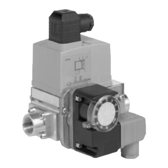
Dungs 3020032 Kurulum, Kullanım ve Bakım Talimatları - Sayfa 12
Endüstriyel Ekipmanlar Dungs 3020032 için çevrimiçi göz atın veya pdf Kurulum, Kullanım ve Bakım Talimatları indirin. Dungs 3020032 17 sayfaları. 1st stage gas trains

INSTALLING THE GAS TRAIN
The gas train leaves the factory ready for installation to the burner's left.
Connection between the gas supply line and train must be made using the gas-in flange (7) supplied,
and fastening screws (8). It is best to tighten screws in a crisscross pattern.
Do not, under any circumstances, install the valve with the coil (10) facing down.
Once installation is complete, you must check for leaks and make sure the gas train is working properly.
PRESSURE LOSS
The gas train pressure loss ∆p is provided from
the diagram; the scales of the volumetric out-
°
put
V
are valid respectively for:
a = air,
n = natural gas (G20),
p = propane (G30),
c = city gas (G140), only for applications not
covered by the Gas Appliances Directive
(90/396/EEC).
The value, provided from the diagram, can be
different according to the pressure stabilizer
adjustment.
The minimum necessary pressure in the network
can be obtained by adding the pressure of the
diagram to the burner pressure losses (see the
burner technical instruction) and the back pres-
sure of the combustion chamber (see the tech-
nical instruction of the heat generator).
PRESSURE STABILIZER ADJUSTMENT (5)
Set the pressure regulator by turning the screw
with a suitable screwdriver: turning clockwise in-
creases pressure delivery, whilst turning anti-
clockwise decreases pressure.
Once you reach the desired nominal pressure
value, close the cap and seal the ends of the wire
with lead, leaving the loop passing through the
holes short.
VALVE ADJUSTMENTS
The output of slow ignition (opening phase of the valve) is adjusted by turning the screw (3) anti-
clockwise in order to increase the output and clockwise to decrease it.
You can adjust the starting gas quantity up to 80% than the main output.
The main output is reached progressively, starting from the ignition output. You can have it by turning
the screw (4) anticlockwise in order to have an increase and clockwise to decrease the output.
LOW GAS PRESSURE SWITCH ADJUSTMENT
Adjust the gas pressure switch (6) by adjusting the graduated scale's wheel, after carrying out all the
other adjustments of the burner with the gas pressure switch adjusted at the beginning of the scale.
Let the burner work at the required output.
Close slowly the gate valve until the pressure, measured on the gas pressure switch gauge, comes down
of 5 - 6 mbar with regard to the working value.
Rotate slowly the gas pressure switch handle until the operation of the same gas pressure switch and
the resultant burner shut-down.
Open completely the gate valve.
3092
Fig. 2
2
GB
D4061
