Dantel B11-44124-00 Kurulum ve Kullanım Kılavuzu - Sayfa 14
Kontrol Ünitesi Dantel B11-44124-00 için çevrimiçi göz atın veya pdf Kurulum ve Kullanım Kılavuzu indirin. Dantel B11-44124-00 16 sayfaları. Data channel termination module

T
E - B
(BW) S
ABLE
ANDWIDTH
INSTRUCTIONS: Go down the left hand column to find the number (1 through 15) that matches the reference total amplitude
(HT) setting from Table D. Follow that row across until a figure is reached that corresponds to or is greater than the measured
bandwidth (BW) ("Checkout" section step number 10). If the BW falls between two numbers on the table, use the lesser
number. Follow that column to the top where it is headed by a number from 1 through 15. That is the reference total
bandwidth (BW) settings for switches S7-5 through S7-8 as given in Table E.
Total BW
Level to be Set
Reference Total
Amplitude
Setting from
CHECKOUT
Section and
Table D (HT)
P
14
AGE
INSTALLATION
2504 H
L
ETTINGS FOR
Z
OSS
LOSS AT 2504 HZ WITH 1004 HZ FOR REFERENCE
ACCUMULATIVE SWITCH SETTINGS S7-5 THROUGH S7-8
0
1
2
3
1
0.00
0.04
0.05
0.07
2
0.00
0.08
0.10
0.13
3
0.00
0.12
0.16
0.20
4
0.00
0.16
0.21
0.27
5
0.00
0.20
0.26
0.33
6
0.00
0.24
0.31
0.40
7
0.00
0.28
0.36
0.47
8
0.00
0.32
0.42
0.53
9
0.00
0.36
0.47
0.60
10
0.00
0.40
0.52
0.67
11
0.00
0.44
0.57
0.73
12
0.00
0.48
0.62
0.80
13
0.00
0.52
0.68
0.87
14
0.00
0.56
0.73
0.93
15
0.00
0.60
0.78
1.00
OPERATION
T
he 44124 Data Channel Termination Module operates when
you apply power. For the most part, operation of the 44124
DCTM consists of observing the front panel LEDs or manually
enabling or disabling the loopback circuit.
You can manually enable the loopback circuit in two ways:
♦
♦
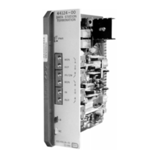
The front panel of the 44124 DCTM has three LEDs (refer to
Fig. 5):
♦
♦
♦
REFERENCE TOTAL BANDWIDTH (BW)
4
5
6
7
8
0.08
0.11
0.15
0.23
0.27
0.16
0.22
0.30
0.46
0.55
0.25
0.33
0.46
0.69
0.82
0.33
0.44
0.61
0.92
1.09
0.41
0.55
0.76
1.15
1.37
0.49
0.66
0.91
1.38
1.64
0.57
0.77
1.06
1.61
1.91
0.66
0.89
1.22
1.84
2.19
0.74
1.00
1.37
2.07
2.46
0.82
1.11
1.52
2.30
2.73
0.90
1.22
1.67
2.53
3.01
0.98
1.33
1.82
2.76
3.28
1.07
1.44
1.98
2.99
3.55
1.15
1.55
2.13
3.22
3.83
1.23
1.66
2.28
3.45
4.10
Set switch S12-3 to ON.
or
Interconnect edge connector pins 1 and 19 (ground).
The green LED indicates applied power to the module.
The red LED indicates loopback and control circuit activity.
The amber LED indicates applied sealing current to the sys-
tem.
9
10
11
12
13
0.30
0.33
0.35
0.39
0.41
0.60
0.67
0.70
0.77
0.83
0.90
1.00
1.06
1.16
1.24
1.20
1.33
1.41
1.55
1.65
1.50
1.67
1.76
1.93
2.06
1.80
2.00
2.11
2.32
2.48
2.10
2.33
2.46
2.71
2.90
2.40
2.67
2.82
3.09
3.30
2.70
3.00
3.17
3.48
3.72
3.00
3.33
3.52
3.87
4.13
3.30
3.67
3.87
4.25
4.55
3.60
4.00
4.22
4.64
4.96
3.90
4.33
4.58
5.03
5.37
4.20
4.67
4.93
5.41
5.79
4.50
5.00
5.28
5.80
6.20
44124-0798 <90-00024>
14
15
0.43
0.44
0.87
0.88
1.30
1.32
1.73
1.76
2.17
2.20
2.60
2.64
3.03
3.08
3.47
3.52
3.90
3.96
4.33
4.40
4.77
4.84
5.20
5.28
5.63
5.72
6.07
6.16
6.50
6.60
