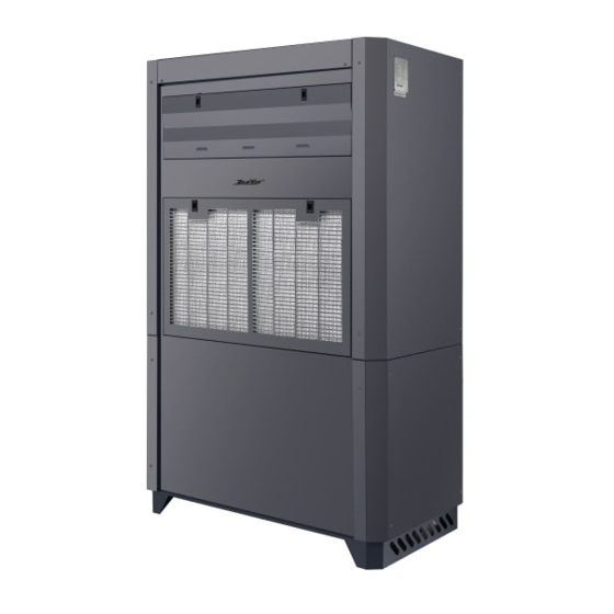
DanVex DEH-5K Manuel - Sayfa 9
Nem Alıcı DanVex DEH-5K için çevrimiçi göz atın veya pdf Manuel indirin. DanVex DEH-5K 19 sayfaları. Industrial condensing dehumidifiers

Correctly designed condensate trap (below)
Condensate system under normal operating conditions:
1. Level A reflects the negative static pressure.
2. Level C is at least 2 times the maximum negative static pressure.
Negative pressure
Condensate pan
The difference between A and C is at least the
negative static pressure of normal operation.
According to experience, the difference is higher
than the negative static pressure of normal
operation. Dirty filter or working fan will cause
higher negative pressure.
3.8.1 Drainage Pipe Test
§
Please have a test after the installation of the drainage pipework.
§
During the test, determine whether the water flow is passing through the pipeline correctly, and carefully observe the
connection to ensure that there is no water leakage at the connection
§
If the unit is installed in a house before renovation, it is recommended to test before ceiling renovation
3.9
Wiring
The electrical connection must be performed by qualified personnel in accordance with the electrical
standards at the location of the equipment.
§
The external control system must be compatible with the low-voltage control circuit of the dehumidification
equipment.
§
The detection element should be installed in a location that is not affected by dr y or humid air and airflow
outside the control area.
§
The fusing power of the power supply fuse must be consistent with the power and type of the installed
dehumidification equipment. The fuse should be installed
§
Installed near the dehumidification equipment. The selection of the power supply cable and the main fuse
should correspond to the correct operating power of the dehumidification unit.
11
The fan is running
§
§ Avoid placing the humidity probe near heat sinks or exposed to direct sunlight, because temperature
changes will affect Actual detection value.
§
The control circuit of the dehumidifier has been marked with different colors to prevent confusion. The
unit design adopts single-phase AC power supply.
§
§ Before the unit is connected to the main power supply, check the single-phase AC power supply to
ensure that the fluctuation range of the supplied voltage does not exceed the set point.
§
Prepare ±10% of marked voltage and frequency. For high load occasions (due to the conversion of larger
electrical equipment) can cause voltage Volatility, this check is particularly important.
3.10 Connection of external sensitive components (control parts)
Dehumidification equipment can be pre-arranged wiring to cooperate with the external control system,
and provide wiring terminals for connecting external control components.
When installing the humidity detection element (sensitive element), its installation position should
comply with the following requirements:
§
Do not install the panel where the relative humidity cannot be accurately detected, such as near a window
or near a water source
§
The humidity detection element should be installed at a position 1 meter to 1.5 meters above the ground
in order to detect representative water in the controlled area.
§
Flat, or laid at the inspection point according to the design requirements.
§
The unit must be grounded and a power isolation switch is provided to ensure that the equipment is cut
off during inspection and ser vice.
§
The dehumidification unit cannot be operated at a voltage and frequency beyond the manufacturing
range.
§
The power supply of the dehumidification unit is equipped with a leakage protection device to make the
unit safer.
-U2
Temp. & Humidity Sensor
A
B
+
-
CONTROLLER
N
L
fan
N
L H M L
C
NONC
12
