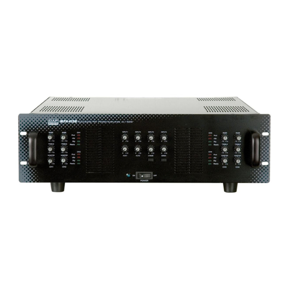
DAPAudio MPA-4150 Manuel - Sayfa 8
Amplifikatör DAPAudio MPA-4150 için çevrimiçi göz atın veya pdf Manuel indirin. DAPAudio MPA-4150 15 sayfaları.
Ayrıca DAPAudio MPA-4150 için: Ürün Kılavuzu (15 sayfalar)

26. 25V terminal.
Connect this terminal to the + terminal of your 25V speaker(s). In case of using several speakers
make sure all speakers are wired in parallel. The total power rating of the 25V-speakers for each
channel should never exceed 250W.
27. 8 Ω terminal.
Connect this terminal to the + terminal of your 8 Ω speaker(s). In case of using several speakers make
sure that the total speaker load is 8 Ω. The total power rating for each channel of the low impedance
speakers should be at least 250W.
28. Common terminal low impedance.
Connect this terminal with the – terminal of your low impedance speaker(s).
29.
GND Screw.
This screw offers a separate ground connection. Can be useful in case of grounding problems.
30.
AC Inlet with integrated fuse holder.
This connector is meant for the connection of the supplied main cord. Connect one end of the
power cord to the connector, the other end to the mains, then turn on the power switch (11) to
operate the unit.
Note: Please make sure that the supply voltage matches the operation voltage before connecting
the unit to mains.
Replace the fuse only with a fuse of same specification (230V:T8A/ 115V: 15A).
31.
Priority remote terminal.
Use this terminal for connecting a remote switch or relay contact. Closing this contact will mute all
inputs except input 1. If the chime button (12) is pressed, a chime signal will be put out.
32.
Siren remote terminal.
Use this terminal for connecting a remote switch or relay contact. Closing the switch will activate the
siren, independent of the siren front switch (13).
33.
Telephone terminal.
Use this terminal to connect a telephone set for broadcasting emergency messages.
34. Impedance/level switch.
Each input can be customized using 4 dipswitches. You can select 4 options:
1. Line/ Mic: Use this switch to set the input impedance/ sensitivity to either Line or Microphone level.
Off position is Line, On position is Mic.
2. Phase: If this switch is in on position, the phase will be inversed.
3. High pass filter: In on position a highpass filter will be activated. The cutoff frequency is 200Hz.
4. 48V phantom power: In on position the input will provide 48V phantom power for a condenser
microphone.
35. Input terminal.
Input for channel 1 – 4. Accepts balanced or unbalanced inputs.
36. 70V terminal.
Connect this terminal to the + terminal of your 70V speaker(s). In case of using several speakers make
sure all speakers are wired in parallel. The total power rating of the 70V-speakers for each channel
should never exceed 250W.
37. Common terminal high impedance.
Connect this terminal with the – terminal of your high impedance speaker(s).
38. 4 Ω terminal.
Connect this terminal to the + terminal of your 4 Ω speaker(s). In case of using several speakers make
sure that the total speaker load is 4 Ω. The total power rating for each channel of the low impedance
speakers should be at least 250W.
6
