Aplisens SGE-25C Kullanıcı Kılavuzu - Sayfa 15
Aksesuarlar Aplisens SGE-25C için çevrimiçi göz atın veya pdf Kullanıcı Kılavuzu indirin. Aplisens SGE-25C 16 sayfaları. Hydrostatic level probes
Ayrıca Aplisens SGE-25C için: Kullanıcı Kılavuzu (20 sayfalar)

Explosion-proof Device Manual EN.IX.SGE
1. Introduction
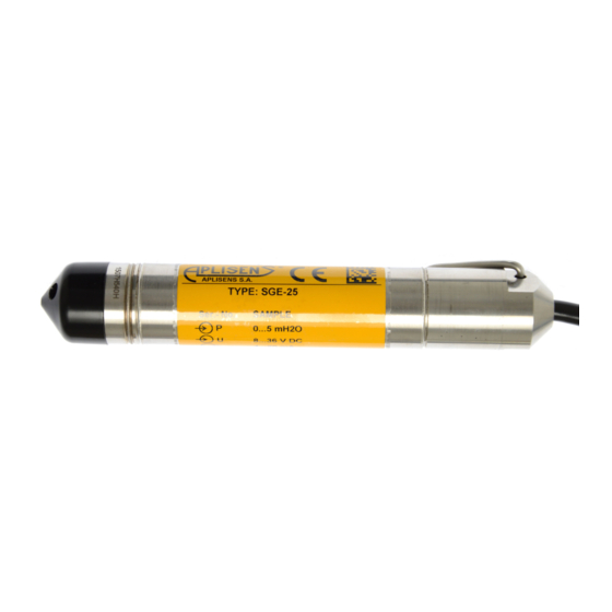
Explosion-proof Device Manual EN.IX.SGE applies only to hydrostatic level probes SGE-25, SGE-25S,
SGE-25C in intrinsically safe version with marking as in point 2 on the nameplate and Ex in the Product
Certificate. When installing and using Ex probes, the User's Manual EN.IO.SGE and Explosion-proof
Device Manual EN.IX.SGE should be used.
2. Using probes in hazardous area
The probes are produced in accordance with the requirements of the following standards:
EN 60079-0:2013-03/A11:2014-03; EN 60079-11:2012; EN 60079-26:2007;
EN 50303:2004.
The probes may operate in areas where there is a risk of explosion, in accordance with the rating of the
explosion protection design:
II 1G Ex ia IIC T4/T5/T6 Ga
II 1G Ex ia IIB T4/T5/T6 Ga (for probe with Teflon sheathed cable)
I M1 Ex ia I Ma
KDB 09ATEX 007X
3. Permissible input parameters (based on data from the certificate KDB
09ATEX007X and validation documentation)
- The probes should be powered from co-operating power supply and measuring devices with
relevant intrinsic-safety certificates, whose parameters of outputs to the danger zone should
not exceed the acceptable power supply parameters for the probes given in points 3a) and 3b).
- Probes in "SA version" should be powered from devices with galvanically separated power
supply.
- Minimum probes power supply 9 V DC.
- The probe is an intrinsically safe device with protection level "ia" when the supply circuit has
protection level "ia" or an intrinsically safe device with protection level "ib" when the supply
circuit has protection level "ib".
a) Acceptable input parameters for power supply with linear characteristics:
Ui = 28 V DC Ii = 0,1 A
b) Acceptable input parameters for power supply with trapezoidal and rectangular characteristics:
Ui = 28 V DC Ii = 0,08 A
c) Input capacity and inductance:
*) The capacitance and inductance of the cable must be taken into account, which for a permanently
connected wire are:
Ck = 0,2 nF/m i Lk = 1 µH/m.
The input capacitance Cw and inductance Lw taking into account the parameters of the cable connected
permanently is:
Cw = Ci + a x Ck = 25 nF + a x 0,2 nF/m; Lw = Li + a x Lk = 400 µH + a x 1 µH/m
Where: - a - length of the cable permanently installed in the probe in metres.
„Pi" for all types of power supply: see table Z1.
Revision.01.A.001/2021.09
HYDROSTATIC LEVEL PROBES
TYPE: SGE–25, SGE–25S, SGE–25C
INTRINSICALLY SAFE VERSION
Ci = 25 nF; Li = 0,4 mH
EN.IO.SGE
EN.IX.SGE
15
