Apogee AD-16 Kullanıcı El Kitabı - Sayfa 12
Medya Dönüştürücü Apogee AD-16 için çevrimiçi göz atın veya pdf Kullanıcı El Kitabı indirin. Apogee AD-16 17 sayfaları. 24-bit 16-channel a/d converter
Ayrıca Apogee AD-16 için: Veri Sayfası (1 sayfalar)

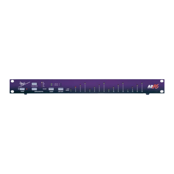
Channel 1-16 OVER LEDs
These LEDs will illuminate when a digital OVER is sensed at the digital output for the respective channel. These
can be set to automatically clear after 2 seconds or infinite hold with rear panel DIP switch #2. The number of
consecutive samples containing "all ones" that constitutes an Over is determined by the setting of DIP Switches
3 and 4. Pressing the OVER CLR button on the left side of the front panel will clear the OVER LEDs.
DIP Switches
The rear panel DIP switches allow a number of system parameters to be set. The switches operate as follows:
DIP Switch
Function
1
UV22HR word length
2
Over infinite hold
3,4
Consecutive Over setting – see below
5
Word Clock output at 88.2/96
6
Sample Freq (fs) locked to ext WC
7, 8
Currently unused
DIP switches number 3 and 4 work together to determine the number of consecutive full scale samples (0dBFS)
required to illuminate the 'over' LEDs (the default setting is both DIPs to DOWN).
SW 3
SW 4
UP
UP
UP
DOWN
DOWN
UP
DOWN
DOWN
WC IN/OUT
The BNC Word Clock IN connector accepts standard Word Clock signals, allowing the AD-16 to be synchro-
nized to an external source when the front panel SAMPLE RATE/SYNC button is set to WC/EXT. DIP Switch 6
allows the AD-16's sample rate to be the same as or twice the rate of the Word Clock input. The WC OUT BNC
connector outputs standard Word Clock signals at a sample rate determined by the SAMPLE RATE/SYNC but-
ton on the front panel. To accommodate systems that require it, DIP Switch 5 can be used to set this output to
the current sample rate or at half the sample rate, when the system sample rate is 88.2 or 96 kHz. See above.
ADAT Optical Outputs
The ADAT outputs support 16 channels at either 44.1/48 kHz via two transmitter outputs, or 88.2/96 kHz via all
four transmitter outputs using the S/MUX protocol. S/MUX is essentially "double-wide mode for ADAT", where
a pair of channels at (for example) 48 kHz will carry one 96 kHz signal. A single 8-channel input then becomes
4 channels in S/MUX mode. When looking at the rear panel, the following illustrates the connection scheme for
either mode. Each box represents one of the four connectors.
ADAT "Normal" Mode
S/MUX Mode
TDIF Connectors
The two TDIF DB25 I/O connectors use only the output half of a standard TDIF cable.
Each cable carries eight channels of audio per bank.
Apogee AD-16 User's Guide
The Rear Panel
Threshold
1
2
3
4
Channels 1-8
Channels 1-8
Channels 1-4
Channels 5-8
ON (UP)
20-bit
ON
half sample rate
fs = 2x WC In freq
Channels 9-16 Channels 9-16
Channels 9-12 Channels 13-16
Page 12
OFF (DOWN)
16-bit
OFF
sample rate
fs = WC In freq
