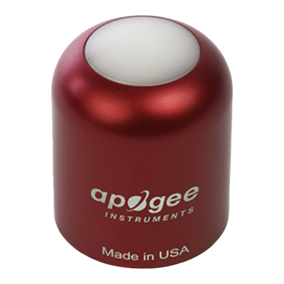
Apogee Instruments S2-432 Kullanıcı El Kitabı - Sayfa 11
Aksesuarlar Apogee Instruments S2-432 için çevrimiçi göz atın veya pdf Kullanıcı El Kitabı indirin. Apogee Instruments S2-432 18 sayfaları. Red-far-red sensors

Register Index
Each register in a sensor represents a value in the sensor, such as a measurement or a configuration parameter.
Some registers can only be read, some registers can only be written, and some can be both read and written. Each
register exists at a specified index in the table for the sensor. Often this index is called an address, which is a
separate address than the sensor address, but can be easily confused with the sensor address.
However, there are two different indexing schemes used for Modbus sensors, though translating between them is
simple. One indexing scheme is called one-based numbering, where the first register is given the index of 1, and is
thereby accessed by requesting access to regis er 1. The other indexing scheme is called zero-based numbering,
where the first register is given the index 0, and is thereby accessed by requesting access to register 0. Apogee
Sensors use zero-based numbering. However, if using the sensor in a system that uses one-based numbering, such
as using a CR1000X logger, adding 1 to the zero-based address will produce the one-based address for the register.
Register Format:
According to the Modbus protocol specification, Holding Registers (the type registers Apogee sensors contain) are
defined to be 16 bits wide. However, when making scientific measurements, it is desirable to obtain a more precise
value than 16 bits allows. Thus, several Modbus implementations will use two 16-bit registers to act as one 32-bit
register. Apogee Modbus sensors use this 32-bit implementation to provide measurement values as 32-bit IEEE
754 floating point numbers.
Apogee Modbus sensors also contain a redundant, duplicate set of registers that use 16-bit signed integers to
represent values as decimal-shifted numbers. It is recommended to use the 32-bit values, if possible, as they
contain more precise values.
Communication Parameters:
Apogee Sensors communicate using the Modbus RTU variant of the Modbus protocol. The default communication
parameters are as follows:
Slave address: 1
Baudrate: 19200
Data bits: 8
Stop bits: 1
Parity: Even
Byte Order: Big-Endian (most significant byte sent first)
The baudrate and slave address are user configurable. Valid slave addresses are 1 to 247. Since the address 0 is
reserve as the broadcast address, setting the slave address to 0 will actually set the slave address to 1. (This will
also reset factory-calibrated values and should NOT be done by the user unless otherwise instructed.)
