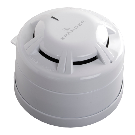
Apollo XPander XPA-CB-14017-APO Devreye Alma Kılavuzu - Sayfa 9
Güvenlik Sensörleri Apollo XPander XPA-CB-14017-APO için çevrimiçi göz atın veya pdf Devreye Alma Kılavuzu indirin. Apollo XPander XPA-CB-14017-APO 19 sayfaları. Diversity loop interface module

Menu options
Menu Level: (1.0)
Device Status
Add New Device
Remove Device
Interface Status
Radio Channels
Fault Status (1.1)
Alarm Status* (1.2)
Battery Level (1.3)
Signal Level (1.4)
Manual Update (1.5)
Ident (1.6)
Type** (1.7)
Menu Level (1.1)
Fault Status
Alarm Status
Battery Level
Signal Level
Manual Update
Ident
For a full range of analogue values please see Appendix A on page 14
This menu shows the status of logged on devices. The loop address as
determined by the XPERT card (1-126), logged on status and the device
type are displayed.
Loop address determined by
the XPERT card or DIL switch
??? = No address assigned
or illegal address
Note: Combined sounder visual indicator base shows two addresses, first address in the detector
followed by the sounder visual indicator as shown below.
Detector
Further information on each device can be viewed by pressing then turning
the Rotary Select Switch.
* Input status on Input/Output Unit
**Combined Sounder Visual Indicator Base only
This menu shows detailed information on the fault status of the device. If
multiple faults are present, these can be viewed by turning the rotary select
switch.
© Apollo Fire Detectors Limited 2015
= Logged On with fire present
L
= Logged On with address assigned
A = Logged On without address assigned
!
= Logged On with fault present
X = Dual address on Interface
Addr 067 L Optic
Addr 004 ! 005 Cmb
9
Optic = Optical Detector
Sound = Sounder Device
I/O = Input/Output Device
Radio = Loop Interface Module
Multi = Multisensor Detector
Heat = A1R Heat Detector
H Temp = CS Heat Detector
MCP = Manual Call Point
Cmb = Combined Sounder Visual
Indicator Base
??? = Unknown Device
Sounder Visual Indicator
