Apollo 65 Series Kurulum Kılavuzu
Denizcilik Ekipmanları Apollo 65 Series için çevrimiçi göz atın veya pdf Kurulum Kılavuzu indirin. Apollo 65 Series 2 sayfaları. Sounder base
© Copyright Apollo Fire Detectors Limited 2006
Apollo Fire Detectors Limited, 36 Brookside Road, Havant, Hants, PO9 1JR, UK
Tel +44 (0)23 9249 2412 Fax +44 (0)23 9249 2754
Email: techsales@apollo-fi re.co.uk Website: www.apollo-fi re.co.uk
4
PP2272/Issue 1
General
This guide describes the installation of the following sounder
Part number
45681-512
45681-513
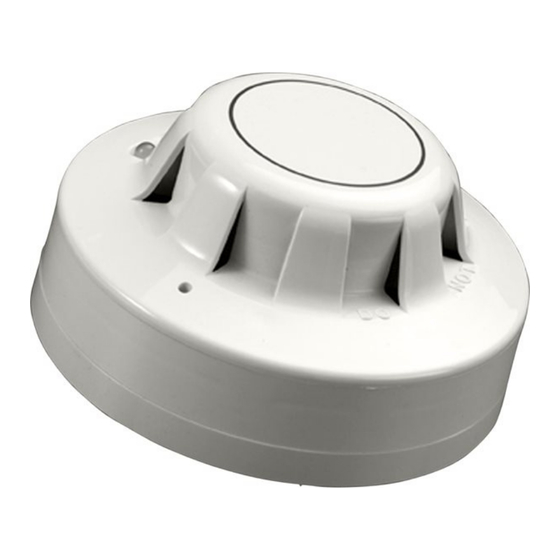
The Series 65 Sounder Base is a high-effi ciency conventional alarm sounder incorporating a
base for the Apollo Series 65 and 60 ranges of detectors. The product offers 32 tones which are
shown in the table on pages 3 and 4.
Mounting and Location
The sounder base can be secured to a conduit box or surface mounted. Sounder Bases should
be located to ensure correct operation of the detector in accordance with the detector
manufacturer's recommendations and local regulations or codes of practice.
Note: The sounder is classifi ed as a Type A device according to EN54-3, ie, is suitable for indoor
use only.
Wiring
The sounder base is designed so that separate detector and sounder circuits can be con-
nected. The sounder circuit is connected using the PCB mounted 4-way terminal block (Fig. 1).
The detector circuit is connected using the terminals marked L1IN, L1OUT and L2 around the rim
of the base in the same way as a standard detector base (Figs 1&2).
Two separate earth terminals are provided to allow the screen termination of earth conduc-
tors to maintain continuity between cables that contain an earth conductor. As this product
is designed for use on conventional systems with separate detector and sounder circuits, the
earths should not be connected together.
From control panel
Fig 1
FIRE DETECTORS LIMITED
Series 65 Sounder Base
Installation Guide
Product Description
Series 65 Sounder Base
Series 65 Sounder Base with diode
+
–R
–R
L1OUT
L1OUT
L2
L2
EARTH
EARTH
–
Detector circuit wiring diagram
1
Remote LED
–R
End-of-line
L1OUT
device
L2
EARTH