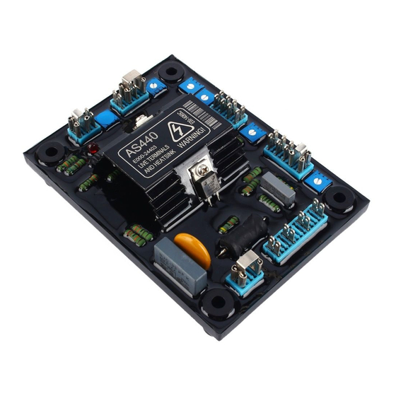
Datacom AS440 Özellikler, Kurulum ve Ayarlamalar - Sayfa 3
Kontrolör Datacom AS440 için çevrimiçi göz atın veya pdf Özellikler, Kurulum ve Ayarlamalar indirin. Datacom AS440 4 sayfaları. Automatic voltage regulator (avr)

CONTROL
VOLTS
TO ADJUST GENERATOR OUTPUT VOLTAGE
TO PREVENT VOLTAGE HUNTING
STABILITY
TO OPTIMISE TRANSIENT PERFORMANCE
STAB SWITCH
UFRO
TO SET THE UFRO KNEE POINT
DROOP
TO SET THE GENERATOR DROOP TO 5% AT OPF
TO OPTIMISE ANALOGUE INPUT SENSITIVITY
VTRIM
TO SET OVER EXCITATION TRIP CUT OFF LEVEL
EXC TRIP
The main functions of the AVR are:
Potential Divider and Rectifier takes a proportion of the
generator output voltage and attenuates it. The potential
divider is adjustable by the AVR Volts potentiometer and
external hand trimmer (when fitted). The output from the
droop CT is also added to this signal. A rectifier converts
the a.c. input signal into d.c. for further processing.
The DC Mixer adds the Analogue input signal the Sensing
signal.
The Amplifier (Amp) compares the sensing voltage to the
Reference Voltage and amplifies the difference (error) to
provide a controlling signal for the power devices. The
Ramp Generator and Level Detector and Driver infinitely
control the conduction period of the Power Control Devices
and hence provides the excitation system with the required
power to maintain the generator voltage within specified
limits.
The Stability Circuit provides adjustable negative ac
feedback to ensure good steady state and transient
performance of the control system.
The Low Hz Detector measures the period of each
electrical cycle and causes the reference voltage to be
reduced
approximately
linearly
presettable
threshold.
A
Light
indication of underspeed running.
T h e S ynchronising circuit is used to keep the Ram p
Generator and Low Hz D e tector locked to the generator
waveform period.
T he Low Pass Filter prevents distorted w aveform s
a ffecting the operation o f th e A V R c o n tro l circuit.
T h e S hort C ircuit D e tector senses the presence o f a
short circuit on the generator o u tp u t and fo rc e s the
P o w er C ontrol Devices into full, conduction. This only
occurs w hen the AV R is pow ered from an auxiliary
winding.
Power Control Devices vary th e am ount o f exciter field
current in response to the erro r signal produced by the
Amplifier.
Suppression com p o n e n ts a re inclu ded to prevent sub
cycle voltage spikes dam aging the A V R com ponents
and also to reduce the am ount o f c o n d u c te d n oise on
the generator terminals.
The Over Excitation Detector c o n tin u o u s ly m o n ito rs the
exciter field voltage and provides signals, to collapse
the output voltage if an over e x c ita tio n
persists for the specified time period.
The Power Supply provides the required voltages for
the AVR circuitry.
SUMMARY OF AVR CONTROLS
FUNCTION
with
speed
below
a
Emitting
Diode gives
c o n d itio n
3 / 4 Page
DIRECTION
CLOCKWISE INCREASES OUTPUT VOLTAGE
CLOCKWISE INCREASE THE DAMPING EFFECT
SEE TABLE ABOVE
CLOCKWISE REDUCES THE KNEE POINT FREQUENCY
CLOCKWISE INCREASES THE DROOP
CLOCKWISE INCREASES THE GAIN OR SENSITIVITY
CLOCKWISE INCREASES THE CUT OFF LEVEL
ADJUSTMENT OF AVR CONTROLS
VO LTAG E ADJUSTMENT
T h e g e n e ra to r o u tp u t v o lta g e is s e t a t th e factory, but
ca n be a lte re d by careful a d ju s tm e n t o f th e V O L T S
c o n tro l on th e A V R boa rd, o r by th e e x te rn a l han d
trim m e r if fitted. If m ajor a d ju s tm e n t is n e ce ssary o r
yo u lose stability, fo llo w th e VO LTAG E SETUP
PROCEDURE'.
Terminals 1 and 2 on the AVR will be fitted with a shorting
link if no hand trimmer is required. Terminals La and Lb are
linked only for special low voltage applications.
W ARNING! Do not increase the voltage above the rated
generator voltage.
If in doubt, refer to the rating plate
mounted on the generator case.
W ARNING!
Do not ground any of the hand trimmer
terminals as these could be above earth potential. Failure
to observe this could cause equipment damage.
W ARNING!
If a replacement AVR has been fitted or re-setting of the
VOLTS adjustment is required, turn the VOLTS control
fully anti-clockwise before running generator.
VO LTAGE SETUP PROCEDURE
For major adjustments and replacing the AVR.
Read and understand th is procedu re before
a tte m p tin g to fo llo w it.
1. B e fo re ru n n in g g e n e ra to r, tu rn the V O LT S control
fully anti-clockwise.
2. Turn remote volts trim m e r ( if fitte d ) to m id w a y
position.
3. Turn STABILITY control to midway position.
4. Connect a suitable voltmeter (0-300V ac) across line to
5. S tart gen era tor set, and run o n no lo a d at nom in a l
frequency e.g. 50-53Hz or 60-63Hz.
6 . If th e red L ig h t E m ittin g Diode (LED) is illum inated,
refer to the Under Frequency Roll Off (UFRO)adjustment.
7. Carefully turn VOLTS control clockwise until rated
voltage is reached.
8. If instability is present at rated voltage, refer to
stability
adjustment,
then re-adjust
necessary.
9. Voltage adjustment is now completed.
voltage
if
