Cayin CS-100A Kullanıcı Kılavuzu - Sayfa 10
Amplifikatör Cayin CS-100A için çevrimiçi göz atın veya pdf Kullanıcı Kılavuzu indirin. Cayin CS-100A 17 sayfaları. Vacuum tube integrated amplifier

Top Panel
3
1
2
4
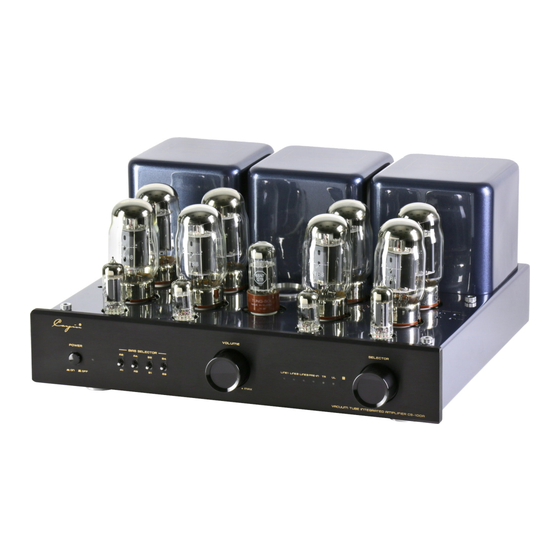
Diagram 3:CS-100A TOP
1.A1、A2、A3、A4、B1、B2、B3、B4:KT88/EL34
Turn the Tube SEL. to position KT88 on the rear panel, if you are going to use KT88 Tube.
Turn the Tube SEL. to position EL34 on the rear panel, if you are going to use EL34 tube.
2.Bias Adjustment (A1、A2、A3、A4、B1、B2、B3、B4)
Used to adjust bias of corresponding power tube (A1、A2、A3、A4 、B1、B2、B3、B4 )
3.V4、V5:12BH7EH Tube
4.
Tube Indicator(
(A1、A2、A3、A4、B1、B2、B3、B4)
5.V2、V3:12AU7EH Tube
6.V1:6SN7GTB Tube
7.BIAS Meter
Bias adjustment for the power tube:
Turn the Bias Selector Switch to its opposite direction without releasing it, adjust the corresponding Bias
Adjustment Swith with flat screwdriver, and inspect the Bias Meter on the top panel to make sure the pointer
keeps in the center. Bias adjustment for A1.A2,A3 and A4 are the same.After all have been adjusted, do it
one more time to make sure all the bias level of A1,A2,A3 and A4 are the same.
Sample of bias adjustment for power tube A1:
1. Turn the Bias Selector Switch A1 to its opposite direction without releasing it.
2. Adjust the corresponding Bias Adjustment Switch A1 with flat screwdriver until the pointer of the bias meter
keeps in the center. The same for A2, A3 and A4.
NOTE:
1.Be careful of the high temperature of the tubes during operation.
2.Replace the tubes carefully and correctly.
3.Tubes must be matched for well function.
9
v1
6
7
/
SN
5
6
7
2
4
Diagram 4
Bias meter when not working
A
Diagram 5
Bias meter during working
Note: When working normally,
the pointer should stay within
the A zone, still , it would move
for the voltage fluctuation.
