elsner elektronik 70456 Teknik Özellikler ve Kurulum Talimatları - Sayfa 2
Kontrol Ünitesi elsner elektronik 70456 için çevrimiçi göz atın veya pdf Teknik Özellikler ve Kurulum Talimatları indirin. elsner elektronik 70456 2 sayfaları. Motor control unit
Control with 230V
Fig. 2
Each terminal contact may be loaded with a
maximum of 10 A.
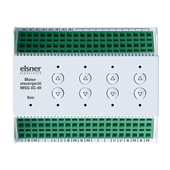
Motor control unit IMSG-UC-4H
Connection example with several groups
Fig. 3
For IMSG-UC-2H
and/or -4H
Each terminal contact may
be loaded with a maximum
of 10 A.
2.4. Notes on mounting and commissioning
Device must not be exposed to water (rain). This could result in the electronic
being damaged. A relative air humidity of 95% must not be exceeded. Avoid bede-
wing.
Pay attention to the correct connection. An incorrect connection can lead to dama-
ge to the motor control unit or to any electronic device connected to it.
3.
Operation
3.1. Central operation
The central input of the IMSG-UC-4H allows, for example, an automatic control
unit, a timeswitch or a normal, unlocked double button (Up/Down) to be connec-
ted. The central command (continuous voltage) always has priority over a move-
ment command from the extension inputs.
LED signals during central control (continuous voltage):
During movement:
Runtime reached:
If there are "Up" and "Down" movement commands at the central input at the same
time, the drive moves up (secure position).
Set operating mode
The central control unit can be set to the operating modes "Latch" (defaulft) or "De-
adman". You can switch between the operating modes using the following buttons
integrated on the device:
If the Latch mode is active, the Network LED is on.
If the Deadman mode is active, the Network LED flashes every second.
Change the operating mode by pressing
Motor control unit IMSG-UC-4H • Version: 28.05.2020 • Technical changes and errors excepted. • Elsner Elektronik GmbH • Sohlengrund 16 • 75395 Ostelsheim • Germany • www.elsner-elektronik.de • Technical Service: +49 (0) 7033 / 30945-250
Channel LEDs in the direction of movement flash every 2
seconds
Channel LEDs in the direction of movement continue to flash
every 2 seconds
Fig. 4
Press the
button of channel
1 and the
button of channel
2 for 5 seconds at the same
time
(channel 1) and
(channel 2) again.
3.2. Individual operation
Manual individual operation of the drives can take place via the integrated Up/
Down buttons at the device or via unlocked double buttons (extension inputs). The
movement mode can be stopped via both buttons (
rent direction of movement.
LED signals during manual control:
During movement:
Channel LED in the direction of move-
ment flashes every second
Runtime reached without interruption:
LED for the direction travelled remains on
Intermediate position reached:
LEDs off
Manual operation can be set to "Standard mode" or "Comfort mode":
3.2.1. Standard mode (default)
•
If a button is pressed for less than 1 second, the drive will move in a step-by-
step fashion. This allows, for example, slats to be positioned precisely.
•
If a button is held for longer than 1 second, the drive moves to its final
position (switching off after 240 seconds of maximum runtime)
This is how you set the Standard mode:
•
Press the
button on the channel to be set for 5 seconds and then
additionally the
button for longer than 1 second
•
To confirm the On LED on the channel flashes 5 times
3.2.2. Comfort mode
•
If a button is held for less than 0.3 seconds, the drive moves to its final
position (switching off after 240 seconds of maximum runtime)
•
If a button is held for longer than 0.3 seconds, but less than 2 seconds, the
drive moves only while the button is pressed and stops immediately when
it is released (deadman function)
•
If a button is held for longer than 2 seconds, the drive moves to its final
position (switching off after 240 seconds of maximum runtime)
This is how you set the Comfort mode:
•
Press the
button on the channel to be set for 5 seconds and then
additionally the
button for longer than 1 second
•
To confirm the Off LED on the channel flashes 5 times
3.3. Individual movement position
The IMSG-UC-4H can store one movement position for each connected drive.
This allows fast and uncomplicated movement to a position that is needed often
(e.g. a shutter position or the partial opening of a window).
3.3.1. Storing a movement position
Storing a position is carried out as follows:
•
Move the drive to the starting/zero position, i.e. close the window, retract the
awning or raise the blinds
•
Press the
and
buttons for three seconds at the same time
•
As feedback the drive moves briefly up and down. You are in now
Programming mode
•
Move to the desired position
•
Store the position by pressing the
and
buttons for 1 second long at the
same time
•
As feedback the drive moves briefly up and down
•
With blind slats, now open the slats to the desired angle. With awnings,
tighten the canvas with
. For windows, you can skip this point.
•
Store by again pressing the
and
buttons for 1 second long at the same
time
•
As feedback the drive moves briefly up and down. The storage is complete
and the IMSG-UC-4H is again in normal mode
Note: As soon as a central command arrives (e.g. because of a wind or rain alarm),
the Programming mode will be interrupted! In this case, please carry out the posi-
tion storage again when the central command is no longer present.
3.3.2. Calling up a movement position
The stored position can be called up by pressing the
channel for 3-6 seconds.
The drive will move to the movement position directly if it is in a secure position
and the runtimes of previous commands have expired. If the drive is in an interme-
diate position, it will move initially to the secure position and then to the stored po-
sition after expiry of the runtime.
4.
Disposal
After use, the device must be disposed of or recycled in accordance with the legal
regulations. Do not dispose of it with the household waste!
2
or
), regardless of the cur-
button of the appropriate