Austria Email EBH-KDW Kullanım ve Montaj Talimatları Kılavuzu - Sayfa 6
Isıtıcı Austria Email EBH-KDW için çevrimiçi göz atın veya pdf Kullanım ve Montaj Talimatları Kılavuzu indirin. Austria Email EBH-KDW 14 sayfaları.
Ayrıca Austria Email EBH-KDW için: Kullanım ve Montaj Talimatları Kılavuzu (14 sayfalar)

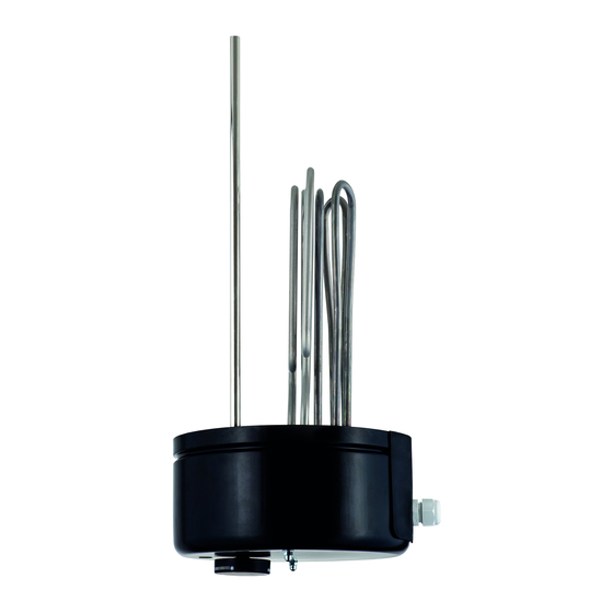
5.2 Assembly of Built-in Heater
In addition to the legally approved regulations, the connecting requirements of the local power company and waterworks
must be complied with.
1. Remove cover on tank.
2. Install heating flange "item 2" in boiler using sealing ring "item 3".
The sensor protection tube of the temperature control must be located above the tubular heating unit(s) when
installed (see information for installation).
3. Attach the heating flange "item 2" using flange screws M12 (max. turning moment 25 Nm ±5).
Tighten the flange screws crosswise.
The screwed connection of the heating unit must be checked and retightened using a turning moment of 2-3
Nm, if necessary.
4. Produce power connection according to the circuit diagram (see section 5.5).
Important – do not forget: connect protective conductor!
5. Mount covering cap "item 1" on tank. Put on enclosed control toggle "item 4", set desired service water tem-
perature.
6. Do not put into operation until the tank is filled with water.
The assembly of the heating installation and the initial start-up must be performed exclusively by an expert, who thereby
accepts responsibility for proper implementation and equipping.
5.3 Information on Corrosion Protection
The built-in heater is designed for installation in enamelled tanks. If the heater is installed in foreign makes, then the supplier
of the boiler must ensure sufficient corrosion protection. First control of the anode is after approx. 2 years operating time.
The protective anodes should be replaced if more than 3/4 of the material have degraded.
The following measure is required in the event of a combination with CrNi (NIRO) tanks or CrNi heat exchangers and instal-
lations in plastic-coated tanks:
a) Disconnect the guard circuit shunt resistor to ensure insulated installation of the heating unit.
b) Disconnect the anode - ground connection cable for the types with anode.
c) Replace the brass sensor tube with a stainless steel sensor tube.
Id.Nr.: 228557-15
6
