austriamicrosystems AS3607 EVAL BOARD Manuel - Sayfa 7
Anakart austriamicrosystems AS3607 EVAL BOARD için çevrimiçi göz atın veya pdf Manuel indirin. austriamicrosystems AS3607 EVAL BOARD 19 sayfaları.

AS3606/7
Preliminary Application Note - Confidential
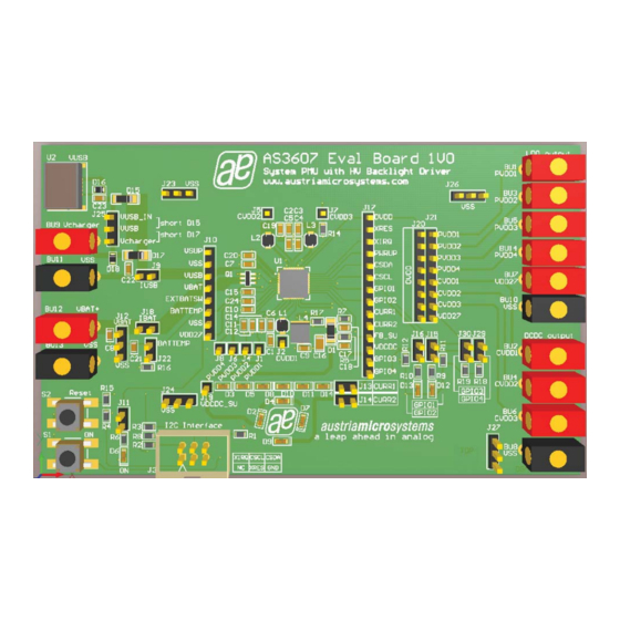
7 AS3607 Evalboard 1V0 connector and jumper locations
Listed below are the various connectors and jumpers.
Jumper
Function
J1
PVDD1
J2
CVDD1
J3
I2C Interface
J4
PVDD2
J5
CVDD2
J6
PVDD3
J7
CVDD3
J8
PVDD4
J9
I USB
J10
measurement pinhead
J11
ON LED
J12
VBAT
J13
CURR1
J14
CURR2
J15
GPIO1
J16
GPIO2
J17
measurement pinhead
J18
I BAT
J20
DVDD
J21
regulator output
J22
BATTEMP
J23, J24,
VSS
J26,J27
J25
disable protection jumper
J29,J30
GPIO3, GPIO4
BU1 –
LDO and DCDC converter output
BU7
BU9
Charger input
U2
Charger input
B12
VBAT+
B13
VBAT-
B8,B10,
VSS
B13
S1
ON
S2
Reset
www.austriamicrosystems.com (dgm)
measurement pinhead of LDO PVDD1
measurement pinhead of DCDC CVDD1
USB-Box connector
measurement pinhead of LDO PVDD2
measurement pinhead of DCDC CVDD2
measurement pinhead of LDO PVDD3
measurement pinhead of DCDC CVDD3
measurement pinhead of LDO PVDD4
current measurement jumper of charge current
status LED connected to VDD27
Battery voltage measurement pinhead
current measurement jumper of CURR1
current measurement jumper of CURR2
if set, LED D12 is connected to GPIO1
if set, LED D13 is connected to GPIO2
current measurement jumper of battery current
DVDD can be supplied with one of the regulators; default: set to VDD27
DVDD can be supplied with one of the regulators; default: set to VDD27
if set, pull up resistor is connected to GPIO3/4
Charger input: 2mm connector
Charger input: USB connector
Battery connector
Battery connector
ON button
Reset button
Revision 1v1 / 20100309
comment
7 - 19
