Bender B91067904 Hızlı Başlangıç Kılavuzu - Sayfa 2
Monitör Bender B91067904 için çevrimiçi göz atın veya pdf Hızlı Başlangıç Kılavuzu indirin. Bender B91067904 12 sayfaları. Front panel for isometer® iso685-s variants

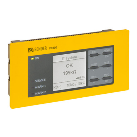
Frontpanel FP200(W)
Frontpanel für ISOMETER® iso685-S Varianten
i
Diese Kurzanleitung gilt für die folgenden Geräteva-
rianten.
Diese Kurzanleitung gilt für:
Modell
FP200
FP200W
2 Schraubbefestigungen
Frontabdeckung 144x72 transparent
Patch-Kabel CAT5e (ohne UL, Temperaturbereich
0...+60 °C) Im Lieferumfang enthalten
FP200-Adapter für Fronttafeleinbau IRDH575
Frontabdeckung 144x96 transparent (IP65)*
* Bei Verwendung der „Frontabdeckung 144x72 transparent (IP65)" muss der
Ausschnitt im Schaltschrank in der Höhe von 66 mm auf 68 mm(+0,7/-0
mm) vergrößert werden.
Bestimmungsgemäße Verwendung
Das Frontpanel FP200(W) ist eine Anzeige- und Bedien-
komponente für das ISOMETER® iso685. Es wird als Front-
tafeleinbau installiert. Das FP200(W) kann nur mit einer
ISOMETER® iso685-S Variante verwendet werden.
Sicherheitshinweise
I
! Elektrischer Schlag! Gefahr eines elektri-
G
efahr
schen Schlages! Stellen Sie vor Einbau des Geräts si-
cher, dass die Anlage spannungsfrei ist. Andernfalls
können Sie einen elektrischen Schlag bekommen.
Außerdem drohen Sachschäden an der elektrischen
Anlage und die Zerstörung des Geräts.
I
! Sachschaden durch unsachgemäße
V
orsicht
Installation! Stellen Sie sicher, dass sich das Haupt-
gerätwährend der Verbindung mit dem Patchkabel
im spannungslosen Zustand befindet. Bei Montage
des FP200W ist es notwendig, die Schrauben mit
Schraubensicherungslack zu sichern, da sie sich bei
erhöhter mechanischer Belastung lockern können.
I
! Sachschaden durch unsachgemäße
V
orsicht
Installation! Schließen Sie das Frontpanel nur an
geeignete Sensor-Varianten an. Ein fehlerhafter
oder unsachgemäßer Anschluss kann zu schweren
Funktionsstörungen oder zum vollständigen Ausfall
des Frontpanels und der Sensor-Variante führen.
2
FP200_D00169_04_Q_INTE/06.2021
Art.-Nr.
B91067904
B91067904W
Zubehör
B91067907
B98060005
B91067906
B91067905
B98060007
Front panel for ISOMETER® iso685-S variants
i
This quickstart guide applies to th following device va-
riants.
This quick-start guide is valid for:
Type
FP200
FP200W
2 screw attachments
Transparent cover 144x72(IP65) *
Patche cabel CAT5e (without UL, Temperature
range 0...+60 °C) included in the delivery
FP200 adapter for front panel mounting
IRDH575
Transparent cover 144x96 (IP65)*
* If the "transparent front cover 144x72 (IP65)" is used, the cutout in the con-
trol cabinet must be increased in height from 66 mm to 68 mm (+ 0.7 / -0
mm).
Intended use
IThe FP200(W) front panel is a display and operator unit
for the ISOMETER® iso685. It is installed as a front panel.
The
FP200(W) can only be used together with the
ISOMETER® iso685-S variant.
Safety instructions
I
! Electric shock! Before installing the unit,
D
anGer
make sure thecomplete system is powered off.
Otherwiseyou may get an electric shock.
Furthermore,the electrical installation may be da-
maged and the device may be destroyed.
I
! Damage to property due to incorrect ins-
c
aution
tallation! Make sure the main unit is powered down
while it is being connected to the patch cable.
When mounting the FP200W it is necessary to secu-
re the screws with thread-locking fluid since they
could loosen when suffering high mechanical load.
I
! Damage to property due to incorrect ins-
c
aution
tallation! Connect the front panel to suitable sensor
variants only. A faulty or improper connection can
result in either serious malfunctions or complete
front panel and sensor variant failure.
Art.-No.
B91067904
B91067904W
Accessories
B91067907
B98060005
B91067906
B91067905
B98060007
