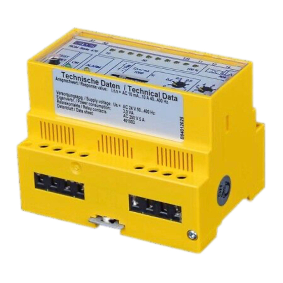
Bender B 94 012 069 Manuel - Sayfa 5
Röleler Bender B 94 012 069 için çevrimiçi göz atın veya pdf Manuel indirin. Bender B 94 012 069 8 sayfaları.

Bedienen
Wird die TEST-Taste länger als zwei Sekunden gedrückt, so wird
ein automatischer Test durchgeführt. Es kann nur ein Test durch-
geführt werden, wenn zuvor keine Fehlermeldung vorhanden
war.
Ein Test-Differenzstrom wird simuliert, nach Ablauf der An-
sprechzeit wird ein Alarm erkannt, das Alarmrelais schaltet, und
die LED „ALARM" leuchtet.
Überwachung externer Messstromwandler
Der Anschluss externer Messstromwandler an das RCM470LY-..
wird überwacht. Bei nicht angeschlossenem Messstromwandler
oder Unterbrechung der Wandlerverbindung blinkt die LED
„ALARM" und das Alarmrelais schaltet. Ein Kurzschluss des Mess-
stromwandlers wird nicht erkannt.
Störungen – Das RCM hat einen Alarm gemeldet
Meldet das RCM einen Alarm, sind der nachgeschaltete Betriebs-
stromkreis und daran angeschlossene Verbraucher auf Isolations-
fehler zu überprüfen. Durch die Wahl des Ansprechwertes und
der Ansprechverzögerung kann das RCM auf den Vorfehlerstrom
der Anlage angepasst werden.
Mögliche Fehlerursachen:
Isolationsfehler auf der Verbraucherseite. (L-PE) (L-Erde)
●
Verbindung zwischen Neutralleiter und Schutzleiter auf
●
der Verbraucherseite
Hohe kapazitive Ableitströme von Verbrauchsgeräten und
●
Leitungen (z. B. durch EMV-Filter)
EMV-Filter oder Überspannungsableiter vor dem Mess-
●
stromwandler installiert
Schaltüberspannungen. Sie entstehen vornehmlich durch
●
im Einschaltmoment beginnende Ladevorgänge. Diese
entstehen, wenn z. B. Betriebsmittel mit Kondensatorbe-
schaltung oder Kabelstrecken eingeschaltet werden. Auch
von Körperschlüssen können sie verursacht werden.
Isolationsfehler zwischen PA-Leiter und Gehäuse (SK I)
●
Verbindung zwischen den Außenleitern der gleichen
●
Phase hinter verschiedenen RCMs
Normen
DIN EN 62020 (VDE 0663): 2005-11, IEC 62020: 2003-11.
„Elektrisches Installationsmaterial - Differenzstrom-Überwa-
chungsgeräte für Hausinstallationen und ähnliche Verwendun-
gen (RCMs).
RCM470LY-.. und RCM475LY-.. sind Differenzstrom-Überwa-
chungsgeräte des Typs A.
Technische Daten
Isolationskoordination nach IEC 60664-1
Bemessungsspannung .......................................................................................................AC 250 V
Bemessungsstoßspannung / Verschmutzungsgrad ............................................................ 4 kV / 3
Spannungsbereiche
Versorgungsspannung U
.............................................................................. siehe Bestellangaben
S
Arbeitsbereich von U
..............................................................................................0,85...1,1 x U
S
Eigenverbrauch ..................................................................................................................... ≤ 3 VA
Messkreis
Messstromwandler, extern (RCM470LY) ............................................ Serie W..., WR..., WS...
Bürde ...................................................................................................................................... 180 Ω
Bürde RCM470LY-72 ............................................................................................................... 18 Ω
TBP401003deen / 09.2008
Operation
By pressing the TEST button longer than two seconds, a test is au-
tomatically carried out. The test cannot be carried out when a
fault message exists.
The test residual current is being simulated, after the expiry of the
response time, an alarm is recognized, the alarm relay switches,
and the ALARM LED lights.
Monitoring external CTs
The connection of external CTs to the RCM470LY-.. is monitored.
When a CT is not connected or the CT connection is interrupted,
the ALARM LED flashes and the alarm relay switches. A short cir-
cuit in the CT will not be recognized.
Faults - The RCM issues an alarm
If the RCM signals an alarm, the operating circuit and the loads
connected to it downstream the RCM are to be checked for insu-
lation faults. By selecting the appropriate response value and the
delay time, the RCM can be adapted to the fault current existing
in the electrical installation during normal conditions.
Possible faults:
Insulation fault on the load side (L-PE) (L-earth)
●
Connection between the neutral conductor and PE con-
●
ductor on the load side
High capacitive leakage currents of loads and connecting
●
leads (e.g. by EMC filters))
EMC filters and surge voltage protectors installed
●
upstream the CT
Switching overvoltages. Frequently occurring when load
●
operations are being started. These overvoltages can be
caused by switching on electrical equipment including
capacitors and long cable runs. They can also be caused by
short circuits.
Insulation fault between the neutral conductor and the
●
enclosure (protection class I)
Connection between phase conductors of the same phase
●
downstream various RCMs
Standards
DIN EN 62020 (VDE 0663): 2005-11, IEC 62020: 2003-11.
"Electrical accessories – Residual current monitors for household
and similar uses (RCMs)".
RCM470LY-.. and RCM475LY-.. are residual current monitors of
type A.
Technical data
Insulation coordination according to IEC 60664-1
Rated insulation voltage ..................................................................................................... AC 250 V
Rated impulse voltage / pollution degree ........................................................................... 4 kV / 3
Voltage ranges
Supply voltage U
.............................................................................................. see ordering details
S
Operating range of U
.............................................................................................0.85...1.1 x U
S
S
Power consumption ............................................................................................................. ≤ 3 VA
Measuring circuit
External measuring current transformers (RCM470LY) .................... W..., WR..., WS... series
Load ........................................................................................................................................180 Ω
Load RCM470LY-72 .................................................................................................................18 Ω
RCM470LY / RCM475LY
S
5
