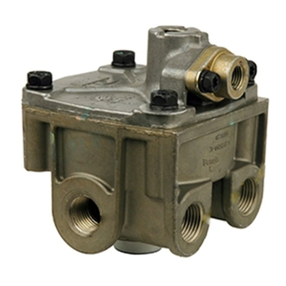
BENDIX AT-3 Kurulum Talimatları
Kontrol Ünitesi BENDIX AT-3 için çevrimiçi göz atın veya pdf Kurulum Talimatları indirin. BENDIX AT-3 4 sayfaları.

Traction Relay
Valve Body
Bracket supplied
varies by kit
number
FIGURE 1 - BENDIX
ATR-6
®
VEHICLE PREPARATION
Follow all standard industry safety precautions, including, but
not limited to, those listed on page two of these instructions.
1. Park the vehicle on a level surface and block the wheels
and/or hold the vehicle by means other than the air
brakes.
2. Drain the air pressure from all vehicle reservoirs.
REMOVAL
1. Prior to disassembly, remove as much contamination as
possible from the exterior of the device.
2. Identify and mark or label the electrical wiring harness
and air hoses and their respective connections on the
valve to aid the technician during reinstallation.
3. Disconnect air hoses from the Bendix
relay valve.
4. Disconnect the electrical connections.
5. Remove the mounting hardware bolts and then remove
the Electronic Control Unit (ECU) from the valve. (See
Figure 1).
Installation
Instructions
Electronic Control
Unit (ECU)
Bendix
ATR-1DC
®
™
traction relay valve
Kit Contents
Key No.
Description
1 . . . . . . R‑12DC
Relay Valve
®
2 . . . . . . AT‑3
Traction Valve
™
3 . . . . . . Bracket (varies by kit)
4 . . . . . . Adapter Harness (varies by kit)
Adapter Harnesses
Vary by Kit
TRACTION RELAY VALVE (WITH EXPLODED VIEW)
™
ATR‑1DC
®
™
Valve Body
Service Port
1/8-27 NPT
Supply Port
6. Discard the original traction control valve body.
INSPECTION
1. Inspect the mounting location for deterioration, wear, and
corrosion. Replace and/or repair as necessary.
INSTALLATION
See the schematic diagrams on page 3 as you plan the
locations to install the replacement components. Take into
consideration the routing of the electrical harnesses, hoses
and orientation of the replacement valves and the remote
mounting of the ECU controller. Note that the schematics
show the new air lines (some indicated as 3/8 inch) that will
be required for this repair.
Note: All torques specified in this document are assembly
torques and can be expected to fall off slightly after assembly.
traction
Do not re‑torque after initial assembly torques fall. For
assembly, use hand tools or torque limited drivers.
Do not use impact driver to install any fittings. Use a
professional grade thread sealant on all air lines connections
to the valves.
Replace Bendix
ATR‑1DC
®
Relay Valve with Bendix
Relay Valve and AT‑3
Through Holes
for Mounting
Supply Port
(2)
1/4-18 NPT
Primary Control
Port 1/4 NPT
Delivery Ports
Traction
™
R‑12DC
®
®
Traction Valve
™
Electrical
Connector
Solenoid Body
Bendix
AT-3
®
™
Traction Valve
(Two Views)
Delivery Port
1/4-18 NPT
Secondary
Control Port
1/4 NPT
Bendix
R-12DC
®
®
Relay Valve
(Horizontal Delivery
Port Version Shown)
Vertical
1
