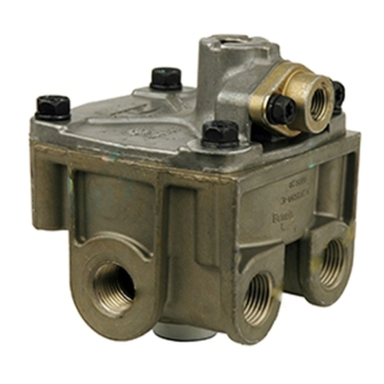
BENDIX ATR1DC ANTILOCK TRACTION RELAY Kurulum Talimatları - Sayfa 3
Kontrol Ünitesi BENDIX ATR1DC ANTILOCK TRACTION RELAY için çevrimiçi göz atın veya pdf Kurulum Talimatları indirin. BENDIX ATR1DC ANTILOCK TRACTION RELAY 4 sayfaları. Antilock traction relay valve
Ayrıca BENDIX ATR1DC ANTILOCK TRACTION RELAY için: Manuel (12 sayfalar)

Original System Schematic
21
11
22
Existing ABS Modulator
Replacement System Schematic
Existing Lines
21
11
22
Existing ABS Modulator
FIGURE 4 ‑ SYSTEM SCHEMATICS
3. For vehicles where the service port is used, apply thread
sealant to the fittings and tighten to 18 ft. lbs. (25 N•m).
Where the fittings were installed using a bench vise, now
bolt the valve onto the vehicle.
4. Reconnect the wire harness to the solenoid using the
identification made during REMOVAL step. Be sure to
check that the harness has sufficient tie-wraps, etc. to
prevent any damage during vehicle operation.
5. Test valve as outlined in Operational and Leakage Tests.
INSTALLATION OF BENDIX
1. In most cases, the brackets supplied in the kit will allow
the existing holes in the frame rail to be used. It will be
necessary to remove two of the relay valve's cap screws
to install the mounting bracket. Torque cap screws to
80‑100 inch pounds.
SYSTEM SUPPLY TANK
(Reservoir)
ECU
Bendix
R-12DC
®
Relay Valve
SYSTEM SUPPLY TANK
(Reservoir)
R-12DC
RELAY VALVE
®
®
Existing ECU
42
Bendix
ATR-1DC
®
Traction Relay
41
Valve
S
D
Remote-Mount Existing ECU
Connector
With Connector Pointed
Down or Sideways Only
ECU
SER
41
D
®
42
S
S
D
3/8" Tubing
2. In cases where the bracket supplied does not include
mounting studs, install the bracket on the vehicle frame
using grade 5 mounting bolts.
3. Inspect all lines and/or hoses for damage and replace
as necessary.
4. Connect air lines to valve (plug any unused ports).
5. Test the valve as outlined in the Operational and Leakage
Test section before returning the valve to service.
™
S
D
Existing ABS Modulator
Bendix
AT-3
®
™
Traction Valve
S
S
D
Existing ABS Modulator
NOTE: Must comply with FMVSS 121 service brake
response time requirements.
Brake
Chamber
Brake
Chamber
3
