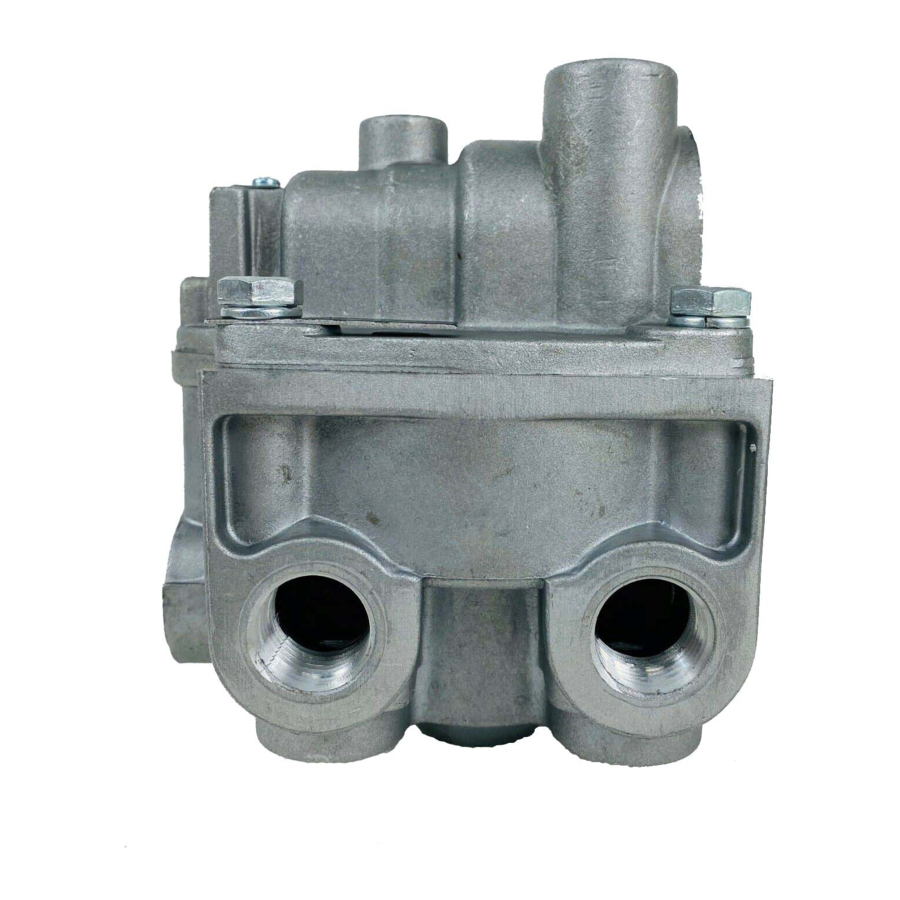
BENDIX BP-R1 BOBTAIL PROP RELAY VALVE Manuel - Sayfa 6
Kontrol Ünitesi BENDIX BP-R1 BOBTAIL PROP RELAY VALVE için çevrimiçi göz atın veya pdf Manuel indirin. BENDIX BP-R1 BOBTAIL PROP RELAY VALVE 11 sayfaları. Bobtail proportioning relay valve

36
37
2
11
12
35
FIGURE 10 - BP-R1
™
BOBTAIL BRAKE PROPORTIONING RELAY VALVE
4. Connect the tractor service and emergency "glad
hands" (hose couplings) to hose couplings that have
been plugged, or alternatively, to a trailer. Build the trac-
tor system air pressure to governor cut-out and make 4
to 5 full brake applications. Check the air fi ttings at the
™
BP-R1
valve for leakage. Tighten as needed.
6
10
30
32
34
31
33
29
13
14
1
9
8
7
6
5
4
3
21
28
19
26
24
27
25
23
........................................... 1
BODY
................................. 2
VALVE COVER
.............................. 3
RETAINING RING
............................. 4
EXHAUST COVER
-
.......................................... 5
O
RING
-
.......................................... 6
O
RING
................................ 7
VALVE SPRING
............................. 8
VALVE RETAINER
............................ 9
VALVE ASSEMBLY
............................... 10
CAP SCREWS
-
........................................11
O
RING
.............................. 12
RELAY PISTON
-
....................................... 13
O
RING
........................... 14
RETURN SPRING
............................ 15
RETAINING RING
(
) ................. 16
DUST SHIELD
IF FITTED
(
) ... 17
EXHAUST PISTON
ORIGINAL STYLE
(
) ...... 17A
EXHAUST PISTON
NEW STYLE
-
................ 18
EXHAUST PISTON O
RING
(
) ...... 19
EXHAUST DIAPHRAGM
IF FITTED
5. With the trailer supply valve (dash control w/red oc-
tagonal button) and system park control (dash control
with yellow diamond button) activated for tractor/trailer
operation, apply, hold, then release the brakes several
times varying the application pressures while watch-
ing the reaction of the gauges installed on the BP-R1
valve. Check that a prompt application occurs and that
it can be held then promptly released.
20
18
16
Early models used
a Diaphragm(19),
Dust Shield(16)
Service Piston(17),
o-ring(21)
17
15
22
20A
18
17A
(
SERVICE PISTON
ORIGINAL STYLE
-
21) ....................... 20
QUIRED O
RING
(
SERVICE PISTON
NEW STYLE
-
) ........................ 20A
REQUIRE O
RING
-
(
SERVICE PISTON O
RING
IF FITTED
....................................... 22
SPRING
............................... 23
SPRING CAGE
...................... 24
BLEND BACK PISTON
-
........................................ 25
O
RING
-
........................................ 26
O
RING
-
........................................ 27
O
RING
................. 28
PROPORTIONING PISTON
-
..................................... 29
O
RINGS
............................ 30
RETAINING RING
-
....................................... 31
O
RING
......................... 32
INLET VALVE SEAT
................................. 33
INLET VALVE
.............................. 34
VALVE SPRING
.............................. 35
SEALING RING
................ 36
EXHAUST COVER SCREW
........................... 37
EXHAUST COVER
Note:
and
15
-
-
RE
-
DOES NOT
) . 21
™
