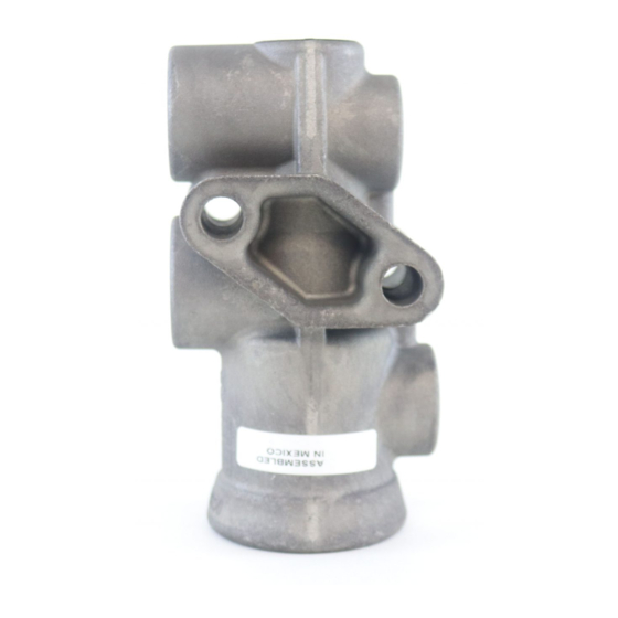
BENDIX TP-3 TRACTOR PROTECTION VALVE Manuel - Sayfa 3
Kontrol Ünitesi BENDIX TP-3 TRACTOR PROTECTION VALVE için çevrimiçi göz atın veya pdf Manuel indirin. BENDIX TP-3 TRACTOR PROTECTION VALVE 4 sayfaları. Tractor protection valve

DISASSEMBLY
EARLY REVISION 80 PSI OPENING PRESSURE
(Figure 1)
1. Remove insert retainer ring (1) Figure 4 with Truarc pliers.
2. Remove insert assembly.
3. Place insert on smooth surface with plunger down.
4. Press down on exhaust diaphragm seat (9).
5. Preload spring (2) may unlock in this manner, if not,
remove exhaust diaphragm cap screw (3), washer (8),
diaphragm (5), and preload spring while holding the seat
down against the valve spring (6) tension.
6. Separate the diaphragm seat, valve spring and plunger
assembly.
7. Remove diaphragm seat o-ring (7).
8. Remove valve retainer (10) and inlet valve (4) from plunger.
Remove plunger o-rings (12) and (13) Figure 3.
LATE REVISION 45 PSI OPENING PRESSURE
(Figure 1)
1. Remove diaphragm seat retainer ring (1) while holding
diaphragm seat (9) in body.
2. Remove date code ring while still holding diaphragm seat
in body.
3. Allow seat to rise until valve spring (6) force is no longer
present.
4. Remove diaphragm seat assembly, valve spring and
plunger assembly.
5. Remove diaphragm seat o-ring (7), Phillips screw (3),
washer (8) and diaphragm (9).
6. Remove valve retainer ring (14), valve retainer (10), inlet
valve (4), and o-rings (12) and (13) from plunger.
CLEANING AND INSPECTION
1. Clean all metal parts in mineral spirits and dry them
completely.
2. Inspect all parts for excessive wear or deterioration.
Inspect valve seats for nicks or burrs. Check the valve
spring for cracks or corrosion.
3. Inspect the bores of the valve housing for deep scuffing
or gouges.
Replace all parts that were discarded and any parts not
found to be serviceable during inspection, using only genuine
Bendix replacement parts.
ASSEMBLY
Before assembling the TP-3
o-ring grooves, body bores and rubbing surfaces with Bendix
silicone lubricant (Pc. No. 291126) or equivalent.
™
valve, lubricate all o-rings,
NOTE: When using pipe thread sealant during assembly
and installation, take particular care to prevent the
sealant from entering the valve itself. Apply the
sealant beginning with the second thread back from
the end.
EARLY REVISION-OPENING PRESSURE 80 PSI
1. Position preload spring (2) then exhaust diaphragm (5)
over stud boss in the diaphragm seat (9).
2. Place washer (8) with lip out on exhaust diaphragm,
install and tighten cap screw (3).
3. Install snap-on valve (4) on plunger (13), position and
force valve retainer (10) down over valve.
4. Install two (2) plunger o-rings (12) and (13) in their proper
grooves.
5. Position valve spring (6) on diaphragm seat (9).
6. Force plunger (3) down into check valve seat until prong
of preload spring snaps into inner cut in plunger and
holds insert assembly together.
7. Position insert seal ring (3) on seat then place complete
™
insert in TP-3
valve body.
8. Using Truarc pliers, install insert retainer ring (1) in TP-3
valve body. Make sure that ring snaps fully into its groove
in the valve body.
LATE REVISION-OPENING PRESSURE 45 PSI
1. Install inlet valve (4) on plunger (3).
2. Position and force valve retainer (10) down over inlet
valve.
3. Install retainer ring (14) beneath the inlet valve retainer.
4. Install both plunger o-ring (12) and (13) in the proper
grooves.
5. Place plunger and valve assembly in valve body.
6. Install Phillips head screw (3), diaphragm washer (8)
(cup side up) and diaphragm (5) into diaphragm seat.
7. Place inlet valve (6) spring into plunger.
8. Install diaphragm seat o-ring in body.
9. Position diaphragm seat assembly over spring and
plunger assembly and force into the body.
10. Replace date code washer and install retaining ring (1)
making sure the retaining ring snaps fully into the groove.
™
TESTING REBUILT TP-3
Perform operating and leakage checks as outlined in
previous section.
VALVES
™
3
