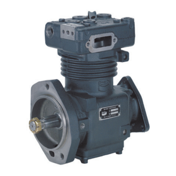
BENDIX BX-2150 Hızlı Başlangıç Kılavuzu - Sayfa 3
Hava Kompresörü BENDIX BX-2150 için çevrimiçi göz atın veya pdf Hızlı Başlangıç Kılavuzu indirin. BENDIX BX-2150 4 sayfaları. Compressor maintenance kit
Ayrıca BENDIX BX-2150 için: Kurulum Talimatları (4 sayfalar)

3. Remove the inlet fitting or air strainer and discard
the gasket (2).
4. Remove the inlet and outlet water lines after draining
the radiator.
5. Remove and retain the four hex head cap screws
from the head. Tap the head with a mallet to break
the gasket seal and remove the head. Remove and
discard the head gasket (14).
6. Remove the unloader stop assembly (3) and discard.
7. Remove the unloader piston assembly (4) and discard.
8. Insert a spanner-type wrench into the holes of the inlet
valve stop (5). Remove and discard.
9. Remove and discard the inlet valve spring (6), inlet
valve (7), inlet valve seat (8), unloader gasket (9), and
unloader spring (10).
10. Using a 9/16" Allen
®
discharge valve seat (11).
11. Remove and discard the discharge valve (12) and the
discharge valve spring (13).
12. Remove and discard the cylinder head gasket (14).
CLEANING
Remove all carbon deposits, rust, and scale from all cavities
in the cylinder head. Use shop air to clear any loose
particles from these recesses. Scrape the body surfaces
of the head and the crankcase taking care not to allow
foreign material to fall into the cylinder.
INSPECTION
1. Inspect the inlet bushing and discharge valve stop for
excessive wear, nicks, and scratches. These surfaces
can be "dressed" with a lapping stone to improve their
condition.
2. If it is apparent that these parts are not salvageable,
obtain replacement parts through a local Bendix
For instructions on the installation of parts not contained
in maintenance kits, refer to SD-01-331.
ASSEMBLY (Refer to Figure 1)
1. Install the unloader stop assembly (3) into the threaded
port on the top of the head above the air inlet cavity.
Torque to 175-225 in-lbs.
2. Turn the head over and install the unloader piston
assembly (4) into the unloader cavity (short stem first).
Install unloader spring (10) (small end first) onto the
long stem of the unloader piston assembly (4). Install
the unloader gasket (9) over the unloader spring and
rest it on the shoulder of the hole in the unloader cavity.
Install the valve seat (8) on top of the unloader gasket
(bevel side of valve seat up). Install the inlet valve (7)
on the valve seat. Install the inlet valve spring (6) on the
inlet valve. Retain with the inlet valve stop (5). Using a
spanner-type wrench, torque to 840-1080 in-lbs.
wrench, remove and discard the
3. Install the discharge valve spring (13) into the cavity of
the discharge valve stop. Install the discharge valve (12) on
top of the discharge spring and retain with the discharge
valve seat (11). Using a 9/16" Allen wrench, torque to
840-1080 in-lbs.
4. Test the head for air leakage prior to installing the head
onto the compressor. Refer to the Air Leakage Tests
section.
5. Make sure the mating surfaces of the head and the
crankcase have been properly prepared. (Refer
to cleaning instructions.) Install the cylinder head
gasket (14) onto the crankcase. Place the head in the
proper position onto the crankcase and retain with the
four 5/16" cap screws. Snug all four cap screws prior to
torquing in a cross pattern to 175-225 in-lbs.
6. Install the inlet fitting or air strainer onto the compressor.
Install the strainer gasket (2) between either component
and the compressor.
7. Replace the governor or air line from the governor onto
the compressor. If the governor is direct mounted onto
the mounting pad of the compressor, install the governor
gasket (1) between the mounting pad and the governor.
8. Connect the discharge air line to the discharge port on
the top of the head.
9. Connect the inlet and outlet water lines to the head and
refill the radiator.
COMPRESSOR TESTING
Vehicles manufactured after the effective date of FMVSS
121, with the minimum required reservoir volume, must
have a compressor capable of raising air system pressure
from 85-100 psi in 25 seconds or less. This test is performed
with the engine operating at maximum recommended
governed speed. The vehicle manufacturer must certify this
performance on new vehicles with appropriate allowances
for air systems with greater than the minimum required
reservoir volume.
outlet.
®
AIR LEAKAGE TESTS
Leakage past the discharge valves can be detected as
follows: Remove the discharge line and cylinder head
from the compressor and apply shop air back through
the discharge port. Coat the discharge valve seat with
soapsuds. Bubble leakage is permitted.
The unloader piston can be checked for leakage as follows:
Build up the air system to governor cut-out and shut off
the engine. (If the head is removed from the compressor,
apply shop air to the governor unloader port.) Listen for
escaping air at the compressor inlet cavity. To pinpoint the
leakage, apply a small amount of oil around the unloader
piston. No leakage is permitted.
3
