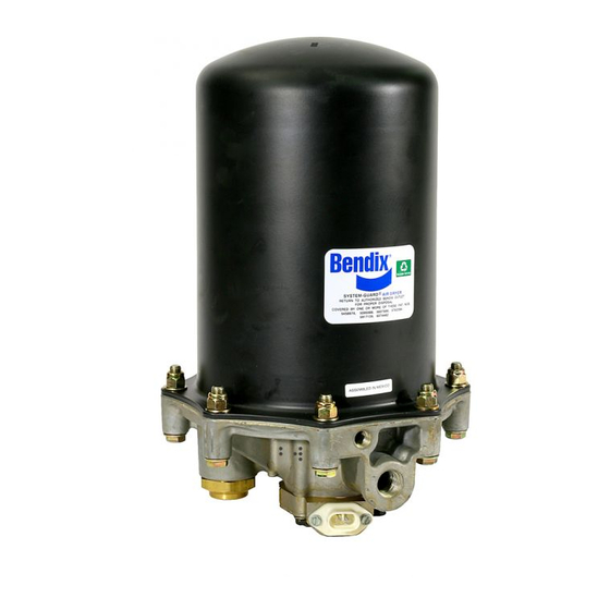
BENDIX AD-9 Hizmet Verileri - Sayfa 5
Nem Alıcı BENDIX AD-9 için çevrimiçi göz atın veya pdf Hizmet Verileri indirin. BENDIX AD-9 20 sayfaları.

3. Perform the Operation & Leakage Tests listed in this
publication.
Every 10,800 hours; 300,000 miles or 36 months:
1. Rebuild the air dryer including the desiccant cartridge.
Note: The desiccant change interval may vary from vehicle
to vehicle. Although typical desiccant cartridge life is three
years, many will perform adequately for a longer period of
time. In order to take maximum advantage of desiccant life
and assure that replacement occurs only when necessary,
it is important that Operation & Leakage Tests be performed.
WARNING!
This air dryer is intended to remove moisture and other
contaminants normally found in the air brake system. Do
not inject alcohol, anti-freeze, or other de-icing substances
into or upstream of the air dryer. Alcohol is removed by the
dryer, but reduces the effectiveness of the device to dry air.
Use of other substances can damage the air dryer and may
void the warranty.
OPERATION & LEAKAGE TESTS
1. Test the outlet port check valve assembly by building
the air system to governor cut-out and observing a test
air gauge installed in the #1 reservoir. A rapid loss of
pressure could indicate a failed outlet port check valve.
This can be confirmed by bleeding the system down,
removing the check valve assembly from the end cover,
subject air pressure to the unit and apply a soap solution
to the check valve side. Leakage should not exceed a 1
inch bubble in 1 second.
2. Check for excessive leakage around the purge valve.
With the compressor in loaded mode (compressing air),
apply a soap solution to the purge valve housing
assembly exhaust port and observe that leakage does
not exceed a 1 inch bubble in 1 second. If the leakage
exceeds the maximum specified, service the purge valve
housing assembly.
3. Close all reservoir drain cocks. Build up system pressure
to governor cut-out and note that AD-9 purges with an
audible escape of air. Fan the service brakes to reduce
system air pressure to governor cut-in. Note that the
system once again builds to full pressure and is followed
by an AD-9 purge.
4. Check the operation of the safety valve by pulling the
exposed stem while the compressor is loaded
(compressing air). There must be an exhaust of air while
the stem is held and the valve should reseat when the
stem is released.
5. Check all lines and fittings leading to and from the air
dryer for leakage and integrity.
AD-9
AIR DRYER
AD-9
END COVER
SIDE VIEW
A two lead, 12 inch, wire harness with attached weather
resistant connector is supplied with all retrofit and
replacement AD-9 Air Dryers. Connect one of the two
leads of the wire harness to the engine kill or ignition
switch. The remaining lead of the wire harness must
be connected to a good vehicle ground. A fuse should
be installed in the power carrying wire; install a 10 amp
fuse for 12 volt heaters and a 5 amp fuse for a 24 volt
heater.
Use 14 AWG wire if it is necessary to lengthen the wire
harness provided.
Make certain all wire splices are waterproofed.
Tie wrap or support all electrical wire leading to the
AD-9.
FIGURE 6 - HEATER AND THERMOSTAT CONNECTOR
6. Check the operation of the end cover heater and
thermostat assembly during cold weather operation as
follows:
A. Electric Power to the Dryer
With the ignition or engine kill switch in the ON posi-
tion, check for voltage to the heater and thermostat
assembly using a voltmeter or test light. Unplug the
electrical connector at the air dryer and place the
test leads on each of the pins of the male connector.
If there is no voltage, look for a blown fuse, broken
wires, or corrosion in the vehicle wiring harness.
Check to see if a good ground path exists.
B. Thermostat and Heater Operation
Turn off the ignition switch and cool the end cover
assembly to below 40 degrees Fahrenheit. Using an
ohmmeter, check the resistance between the elec-
trical pins in the female connector. The resistance
should be 1.5 to 3.0 ohms for the 12 volt heater as-
sembly and 6.8 to 9.0 ohms for the 24 volt heater
LOWER
MOUNTING
BRACKET
FEMALE
CONNECTOR
MALE
CONNECTOR
LATCH MUST BE
INSERTED UNTIL
IT SNAPS OVER
TAB ON MATING
CONNECTOR
END VIEW
5
