GAC ESD5500-II Hızlı Başlangıç Kılavuzu - Sayfa 4
Kontrol Ünitesi GAC ESD5500-II için çevrimiçi göz atın veya pdf Hızlı Başlangıç Kılavuzu indirin. GAC ESD5500-II 8 sayfaları. Speed control unit
5
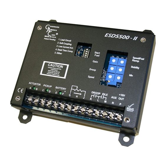
OTHER SETTINGS
DIP switches allow you to set the following settings on or off as required.
These must be set prior to startup. These include [Factory setting]:
•
1 – Lead / Lag Circuit, adjusts for fast instability in the system [ON]
•
2 – Soft Coupling, eliminates fast erratic governor behavior caused by very
soft or worn couplings in the drive train between the engine and generator.
[OFF]
•
3 – Low Current Actuator, for use with light force/low current actuators
including T1 ATB, ALR/ALN, 100-, 103-, and 104-Series actuators. [OFF]
•
4 – Dead Time Compensation, adjusts for irregularity in engine speed
above and below 3Hz. [ON]
•
5 - Dither, reduces actuator sticking or increase stability in contaminated/
dirty environments. [OFF]
6
ADJUSTMENTS BEFORE ENGINE STARTUP
Set the following adjustments before starting the engine.
Gain
Middle Position [50%]
Stability
Middle Position [50%]
Speed
Middle Position [50%]
Start Fuel
Full CW (Maximum Fuel) [100%]
Speed/Fuel Ramp
Full CCW (Fastest) [100%]
7
START THE ENGINE
The speed control unit governed speed setting is factory set at approximately engine idle speed. (1000 Hz., Speed sensor signal or
600 RPM)
Crank the engine with DC power applied to the governor system. The actuator will energize to the maximum fuel position until the
engine starts. The governor system should control the engine at a low idle speed.
8
SPEED SETTING
The speed set point is increased by clockwise rotation of the Speed adjustment control. Remote speed adjustment can be obtained with an
optional 5K Speed Trim Control.
Droop
Speed
9
START FUEL & IDLE ADJUSTMENT
1.
Place the engine in idle by connecting Terminals M & G and placing the external selector switch in
the Idle position.
2.
Adjust the Idle or operating speed for as low a speed setting as the application allows. (CCW turn
to lower speed)
3.
Adjust the Start Fuel CCW until engine speed begins to fall. Increase the Start Fuel slightly so that
the idle speed is returned to the desired level.
4.
Stop the engine.
5.
If idle is not set using the external selector switch as described in STarT fUeL aDJUSTmenT,
place the optional external selector switch in the Idle position.
6.
The idle speed set point is increased by the clockwise rotation of the Idle adjustment control.
When the engine is at idle speed, the speed control unit applies droop to the speed controller to
ensure stable operation.
5.650
(144)
5.000
(127)
Idle
noTe
STarT fUeL aDJUSTmenT
IDLe SPeeD SeTTInG
G
OVERNORS
A
MERICA
C
®
ORP.
MADE IN USA
Patent Pending
1. Lead Circuit
2. Soft Coupling
3. Low Current Act.
4. Dead Time Comp.
5. Dither
Contact GAC with any questions on these settings.
[Factory setting]
CAUTION
ENGINE SPEED CONTROL
COMPONENT. WHEN INSTALLING
OR SERVICING REFER TO
PRODUCT PUBLICATION.
ACTUATOR
PICK-UP
A
B C
[Factory setting]
The Speed potentiometer is a 25 turn potentiometer
ESD5500-II Fusion Series Speed Control Unit 1-2020-A4
4
1
ON
2
ON
ON
3
4
ON
ON
5
Start
Speed/Fuel
Fuel
Stability
Gain
BATTERY
-
+
Droop
D E
F
G
H
Speed
Start
Fuel
Gain
Droop
Speed
Governors America Corp. © 2021 Copyright All Rights Reserved
ESD55
Start
Fuel
Gain
Droop
Speed
Ramp
IDLE
DROOP
Idle
J
K
L
M
Speed/Fuel
Ramp
Stability
Idle
PIB2180