GAC ESD5520E Manuel - Sayfa 6
Kontrol Ünitesi GAC ESD5520E için çevrimiçi göz atın veya pdf Manuel indirin. GAC ESD5520E 9 sayfaları. Speed control unit
Ayrıca GAC ESD5520E için: Manuel (9 sayfalar)
11
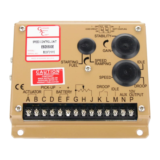
ADDITIONAl FEATURES AND OPTIONAl WIRINg
IDLe SPeeD SettInG
If the IDLE speed setting was not adjusted as detailed in Section 9 Starting
Fuel Adjustment, then place the optional external selector switch in the IDLE
position.
The idle speed set point is increased by the clockwise rotation of the IDLE
adjustment control. When the engine is at idle speed, the speed control unit
applies droop to the governor system to ensure stable operation.
If not using the idle method, you can lower idle to the bare minimum (even if it's
not being used) for smoke reduction.
LeaD cIrcuIt & Soft couPLInG
Switch 1(C1) controls the Lead Circuit. The normal position is ON.
Move the switch to the OFF position if there is fast instability in the
system.
Switch 2(C2) controls a circuit designed to eliminate fast erratic gover-
nor behavior, caused by very soft or worn couplings in the drive train
between the engine and generator.
The normal position is OFF. Use the ON position if you experience
fast erratic engine behavior between the engine and generator due to
a soft coupling.
acceSSorY InPut
The Auxiliary Terminal N accepts input signals from load sharing units,
auto synchronizers, and other governor system accessories, GAC ac-
cessories are directly connected to this terminal.
note
Terminal N is sensitive (145 Hz/V). Accessory connections
must be shielded.
When an accessory is connected to Terminal N, the speed will de-
crease and the speed adjustment must be reset.
If the auto synchronizer is used alone, not in conjunction with a load shar-
ing module, a 3 Ω resistor should be connected between Terminals N and
P. This is required to match the voltage levels between the speed control
unit and the synchronizer.
acceSSorY SuPPLY
The +10 volt regulated supply, Terminal P, can be utilized to provide power to GAC governor system accessories. Up to 20 mA of current can
be drawn from this supply. Ground reference is Terminal G.
A short circuit on this terminal can damage the speed control unit.
Do not connect Terminals N and P directly to each other.
IDLE
SPEED
DROOP
C1 OFF
ON
C2
SOFT COUPLING
LEAD CIRCUIT
OFF
ON
6
ESD5500E Series Speed Control Unit 2-2021-F2 PIB1002
Governors America Corp. © 2021 Copyright All Rights Reserved
IDLE
SPEED
DROOP
2750 Hz x 60 seconds = 1500 RPM
110 Teeth
LEA